3.4 Implementing Wi-Fi Connection and Applications with XIAO ESP32C3
Rather than saying computers have changed the world, it would be more accurate to say that computer networks have. The emergence of networks has truly made computers different from previous tools. The sharing and exchange of information have made computers an epoch-making product. In this section, we will learn how to implement network requests using XIAO ESP32C3, which has Wi-Fi and Bluetooth (BLE) capabilities. This includes connecting XIAO to a Wi-Fi network, pinging specified websites, and issuing GET/POST requests using the HTTP protocol.
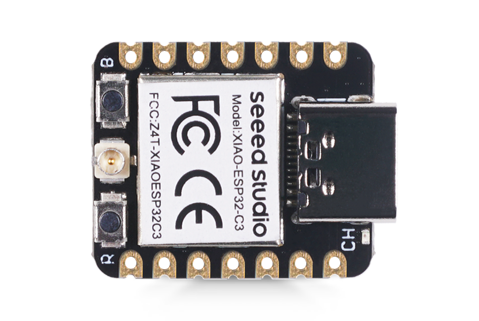
Seeed Studio XIAO ESP32C3
3.4.1 Background Knowledge
3.4.1.1 OSI Reference Model (Network Seven-Layer Model)
OSI (Open System Interconnect) is commonly known as the OSI reference model or network seven-layer structure, which is the network interconnect model researched by the ISO organization in 1985. This architectural standard defines the seven-layer framework (physical layer, data link layer, network layer, transport layer, session layer, presentation layer, and application layer) for network interconnection. For ease of understanding, the following diagram uses a logistics transportation process to correspond to each layer of the OSI model.
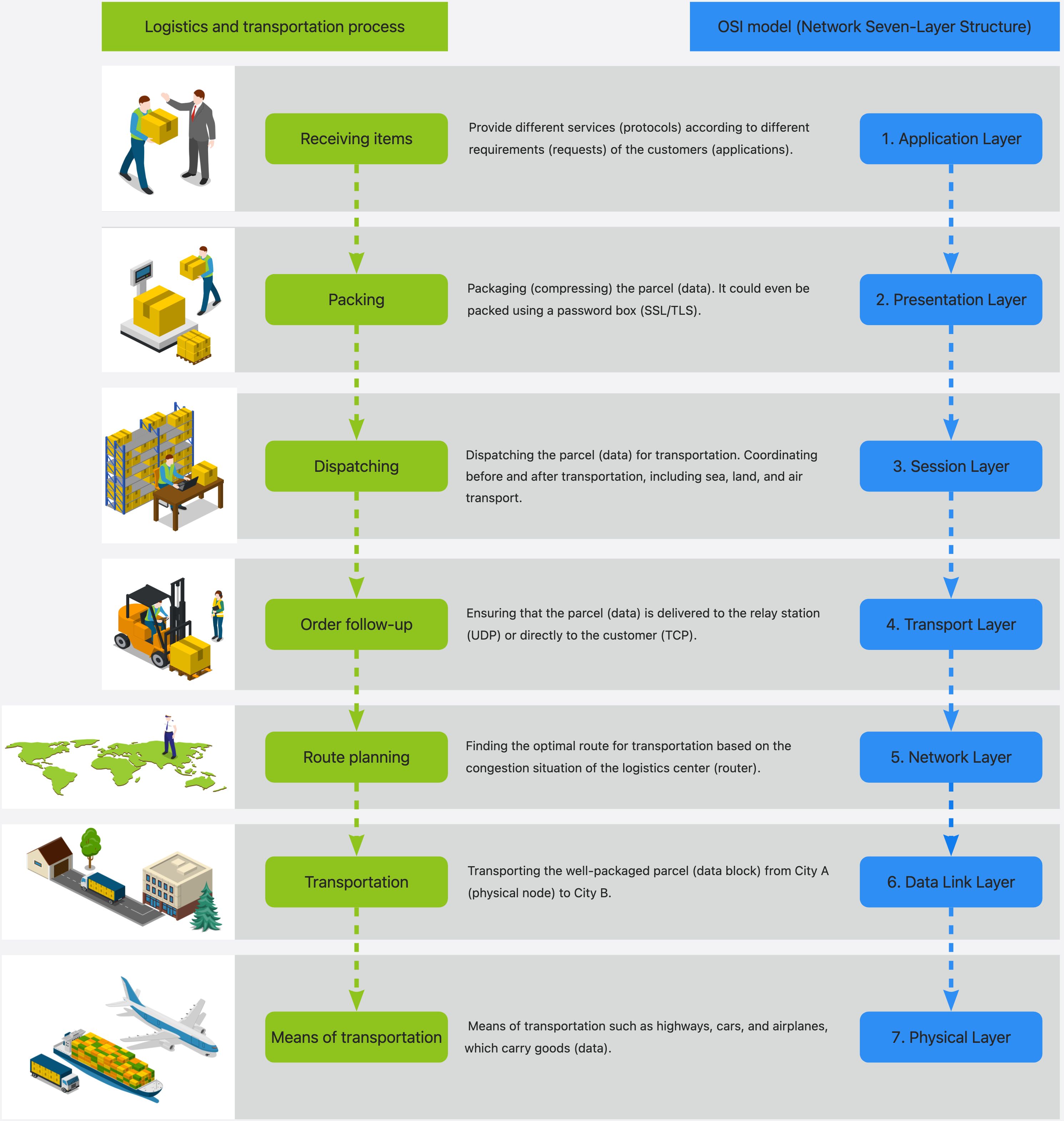
The following knowledge will use the concepts of these layers.
3.4.1.2 ICMP (Internet Control Message Protocol) and ping Command
ICMP (Internet Control Message Protocol) is a sub-protocol of the TCP/IP protocol suite. It is used to transmit control messages between IP hosts and routers. Control messages refer to messages about the network itself, such as whether the network is available, whether the host is reachable, whether the route is available, etc. Although these control messages do not transmit user data, they play an important role in the transmission of user data.
🎓 Learn more: visit the Wikipedia entry on ICMP.
We often use the ICMP protocol in the network, such as the Ping command (available in both Linux and Windows) we often use to check whether the network is available. This Ping process is actually the working process of the ICMP protocol. ping can test the connection speed between two devices and accurately report the time it takes for a packet to reach its destination and return to the sender’s device. Although ping does not provide data about routing or hops, it is still a useful metric for measuring latency between two devices. Below we will learn how to implement ping requests on XIAO ESP32C3.
Before starting this attempt, we need to learn how to connect XIAO ESP32C3 with your Wi-Fi.
3.4.2 Task 1: Using Wi-Fi Network on XIAO ESP32C3
XIAO ESP32C3 supports Wi-Fi connections with IEEE 802.11b/g/n. The following will introduce the basic knowledge of using Wi-Fi on this board.
⚠️ Note:
Be careful when attempting to use the XIAO ESP32C3 development board as a hotspot (access point). Overheating issues may occur and lead to burns.
Hardware Setup: Connect an Antenna to the XIAO ESP32C3 and Connect it to Your Computer
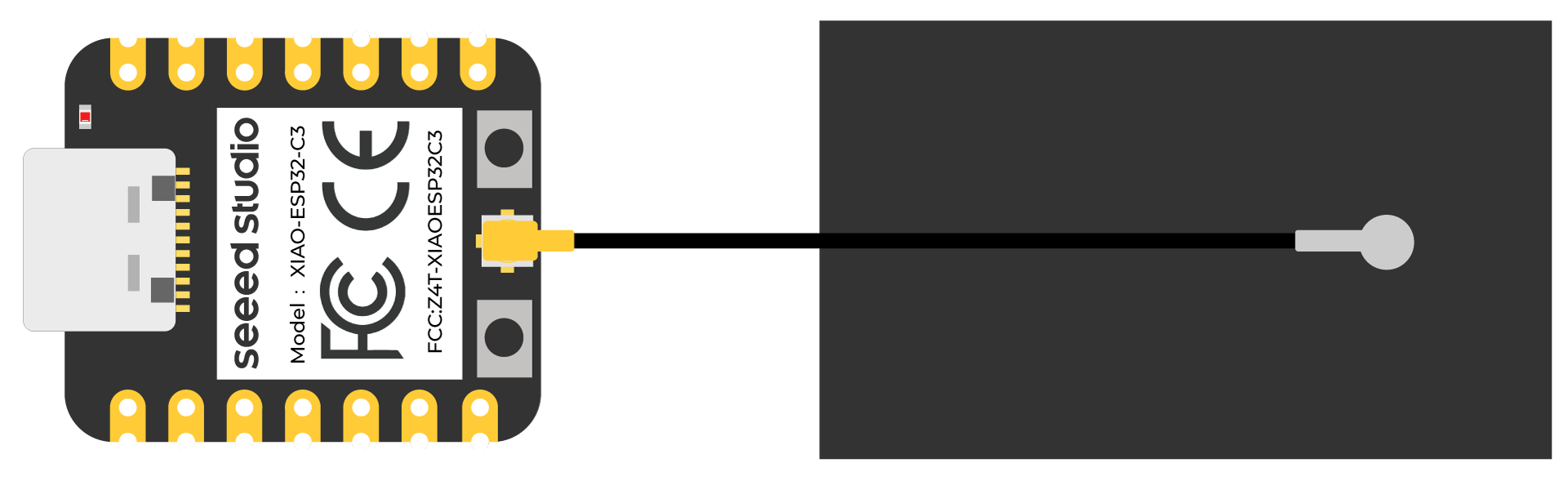
Step 1. Connect the provided Wi-Fi/Bluetooth antenna to the IPEX connector on the development board.
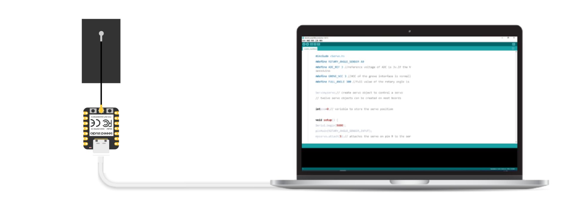
Step 2. Connect the XIAO ESP32C3 to your computer via a USB Type-C data cable.
Software Setup: Add the ESP32 Board Package to the Arduino IDE
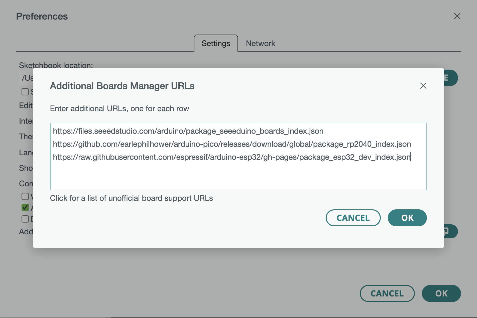
Step 1. Open the Arduino IDE preferences to add the Board Manager URL.
- For Windows users, first open your Arduino IDE, click on “File→Preferences” in the top menu bar, and copy the following URL into “Additional Board Manager URLs”.
- For Mac users, first open your Arduino IDE, click on “Arduino IDE→Preferences” in the top menu bar, and copy the following URL into “Additional Board Manager URLs”.
For Seeed Studio XIAO ESP32C3, copy the link below:
https://raw.githubusercontent.com/espressif/arduino-esp32/gh-pages/package_esp32_dev_index.json
to the Board Manager URL bar and confirm, as shown in the figure below.
Step 2. In the Arduino IDE menu, click “Tools→Board→Board Manager”, type “esp32” into the search bar, find the latest version of ESP32 Arduino in the resulting entries, and click “Install”. When the installation starts, you will see an output pop-up. Once the installation is complete, the “Installed” option will appear.
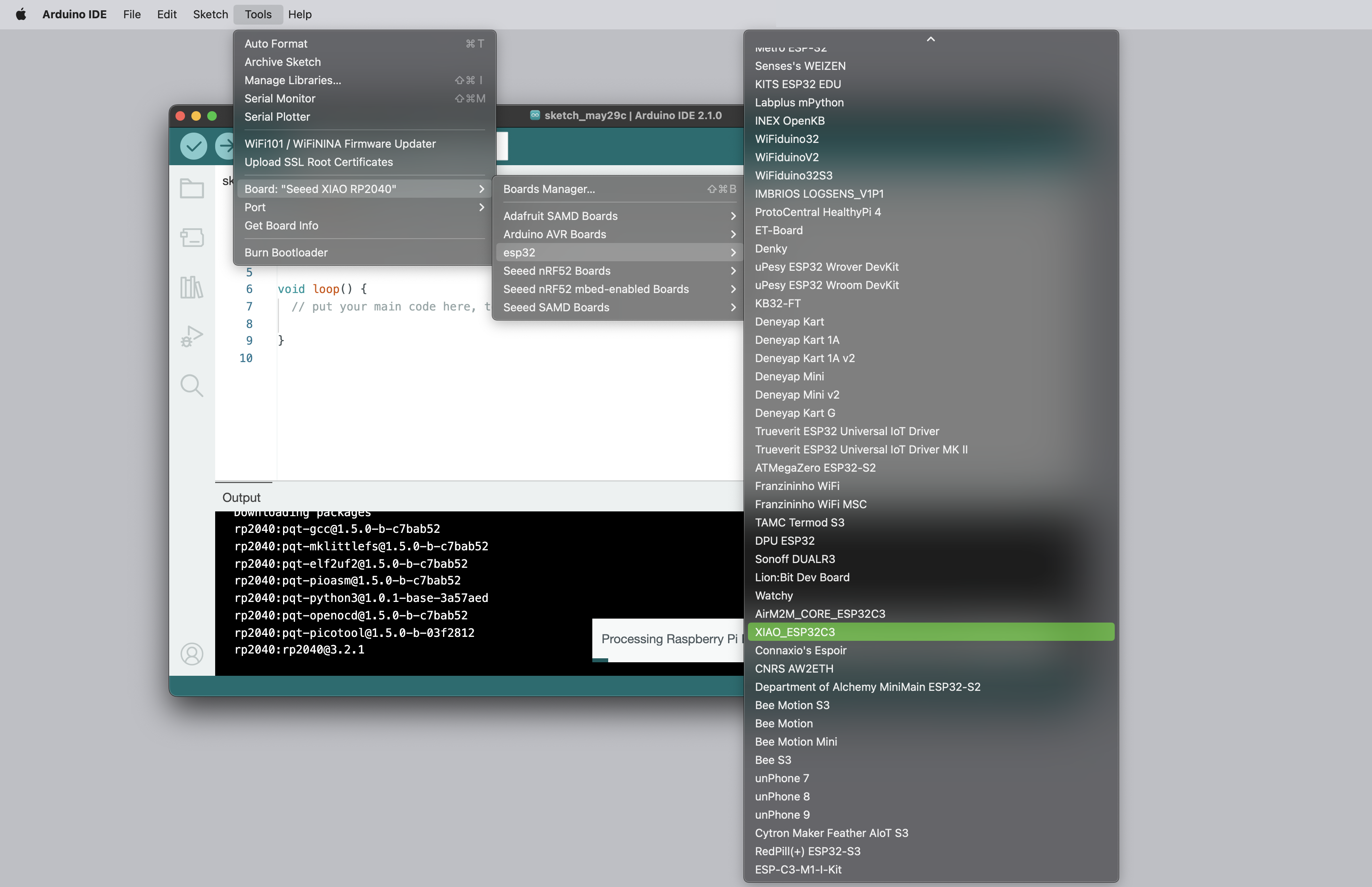
Step 3. Select the Board.
Navigate to “Tools > Board > ESP32 Arduino” and select “XIAO_ESP32C3”. The list will be a bit long, and you will need to scroll down to find it, as shown in the figure below.
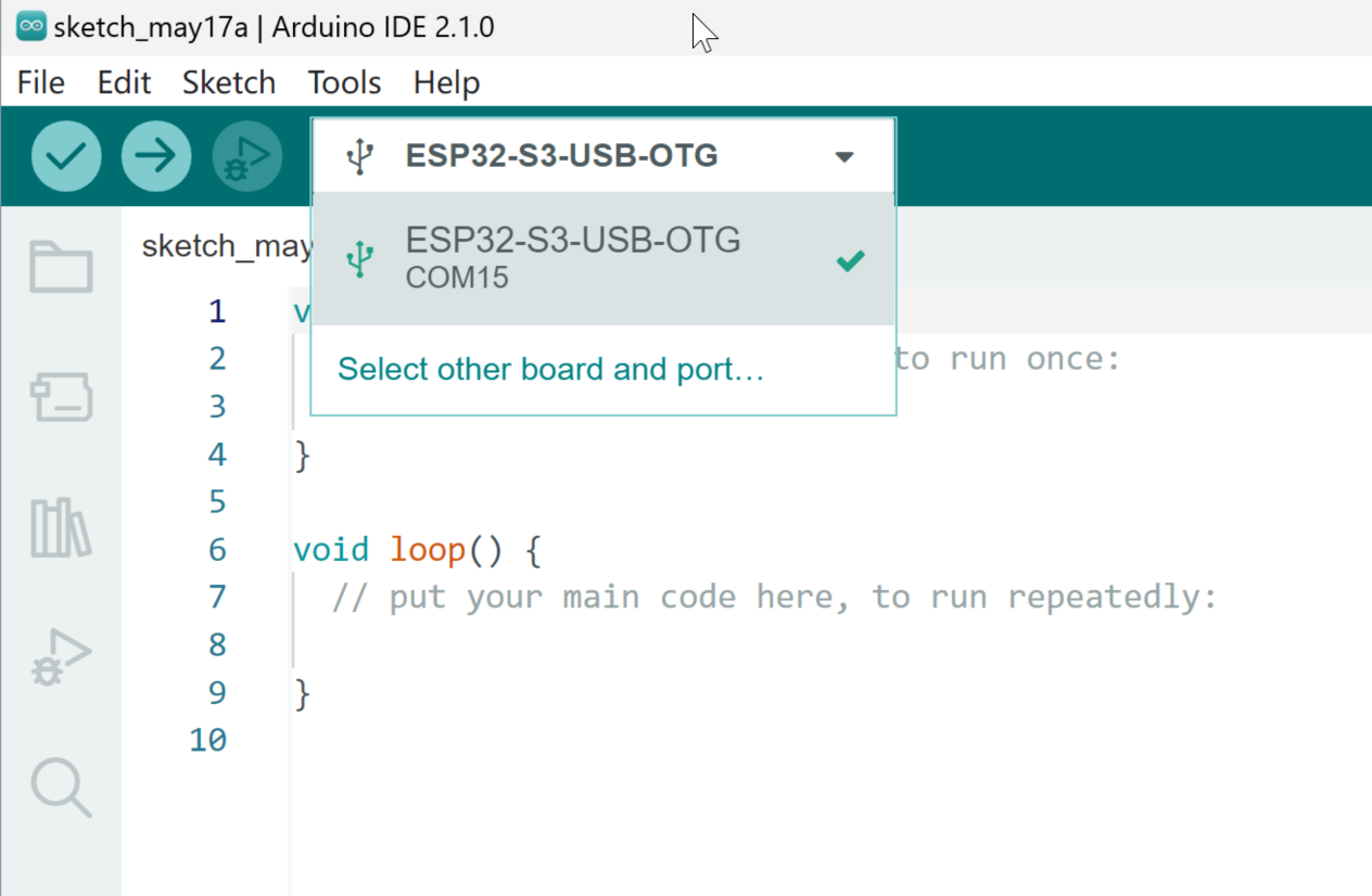
Step 4. Add Port.
Check if the port connection is correct in the Arudino IDE. If not, you need to manually select.
- For Windows systems, the serial port is displayed as “COM+number”, as shown in the figure below.
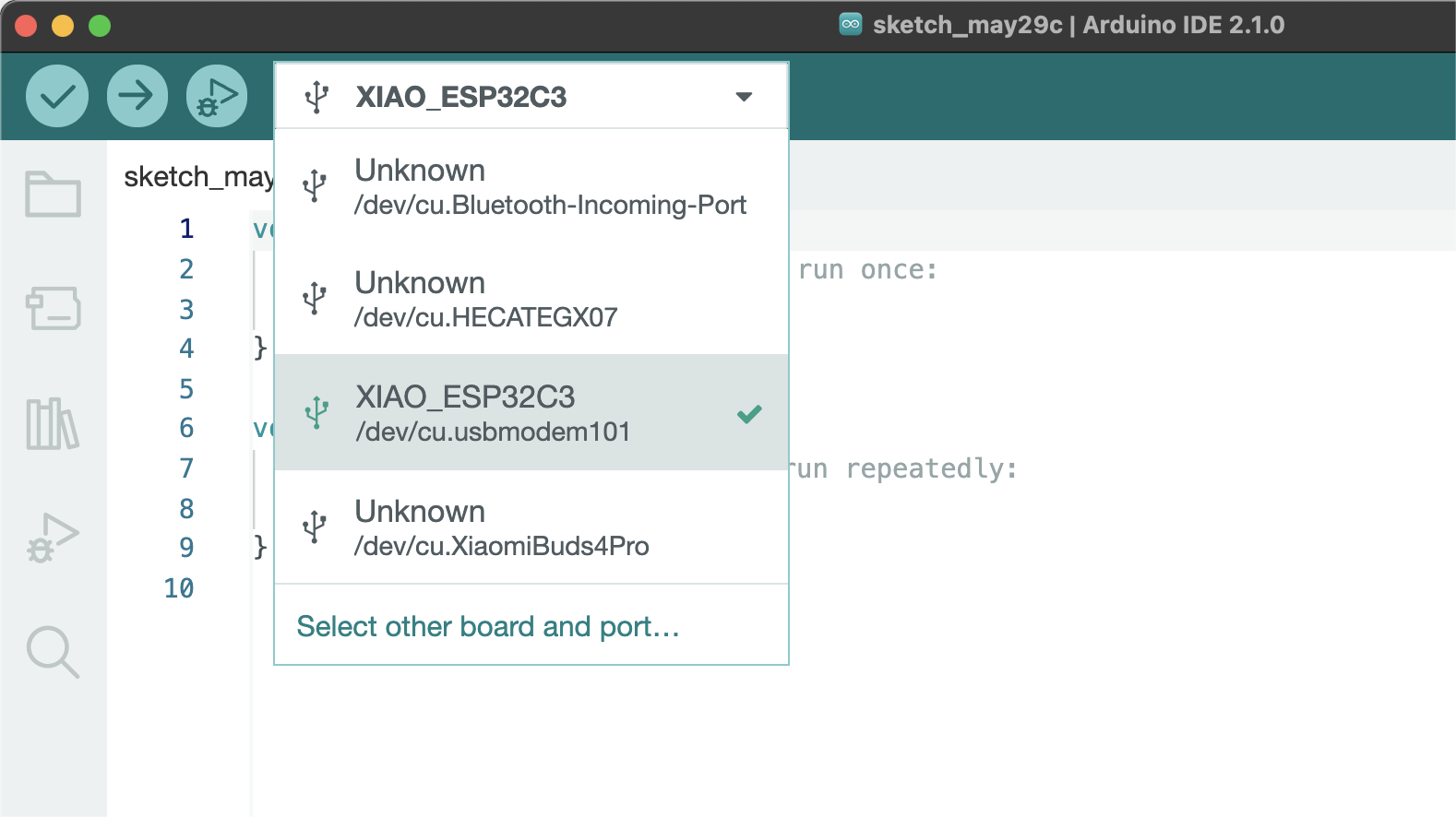
- On Mac or Linux systems, the port name is typically
/dev/tty.usbmodem+numberor/dev/cu.usbmodem+number, as shown in the figure below.
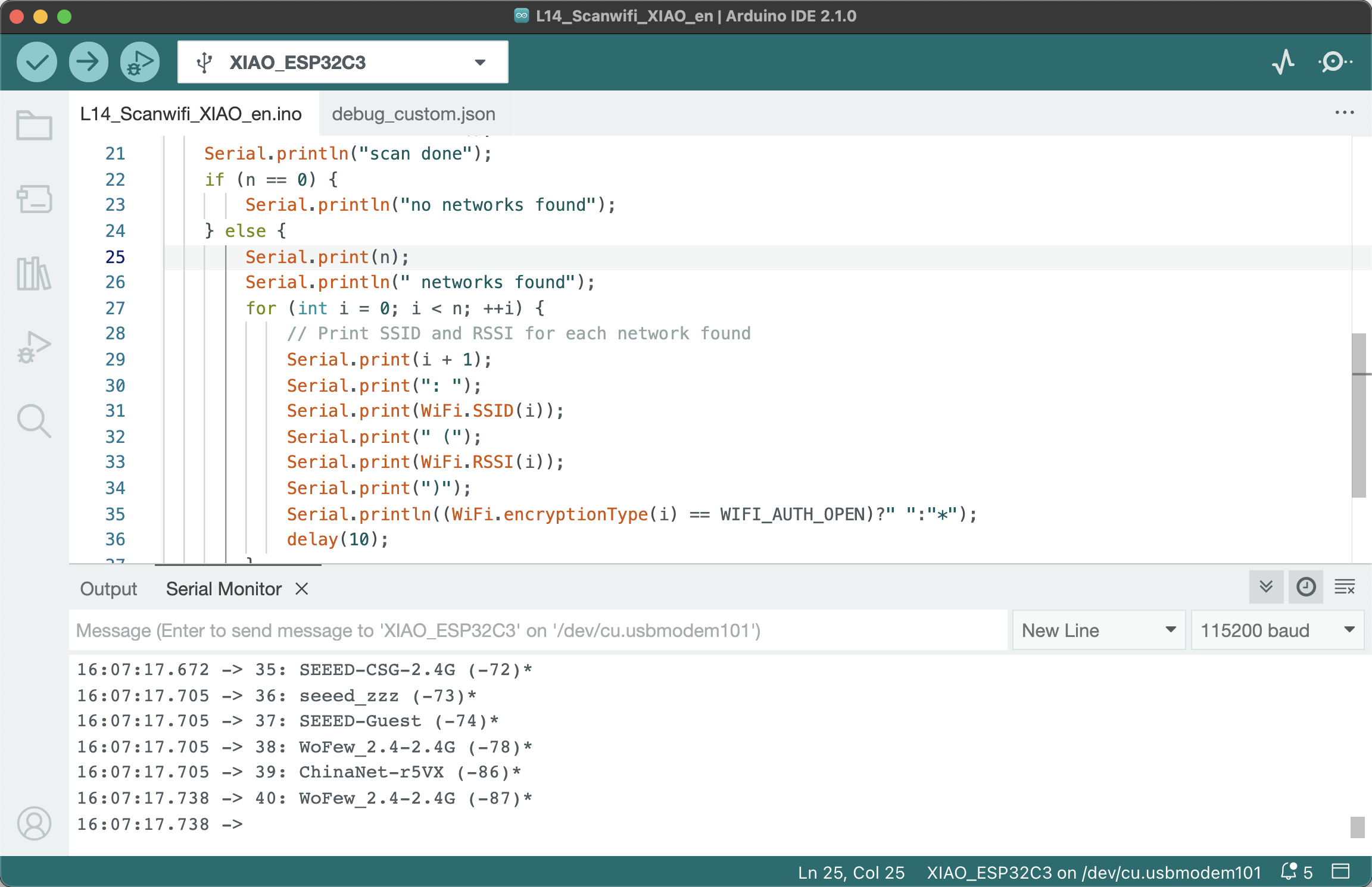
Scanning Nearby Wi-Fi Networks (STA Mode)
In this example, we will use the XIAO ESP32C3 to scan for available Wi-Fi networks in the area. The development board in this example will be configured in STA mode.
Step 1. Copy and paste the code below into the Arduino IDE.
#include "WiFi.h"

void setup()
{
    Serial.begin(115200);

    // Set WiFi to station mode and disconnect from an AP if it was previously connected
    WiFi.mode(WIFI_STA);
    WiFi.disconnect();
    delay(100);

    Serial.println("Setup done");
}

void loop()
{
    Serial.println("scan start");

    // WiFi.scanNetworks will return the number of networks found
    int n = WiFi.scanNetworks();
    Serial.println("scan done");
    if (n == 0) {
        Serial.println("no networks found");
    } else {
        Serial.print(n);
        Serial.println(" networks found");
        for (int i = 0; i < n; ++i) {
            // Print SSID and RSSI for each network found
            Serial.print(i + 1);
            Serial.print(": ");
            Serial.print(WiFi.SSID(i));
            Serial.print(" (");
            Serial.print(WiFi.RSSI(i));
            Serial.print(")");
            Serial.println((WiFi.encryptionType(i) == WIFI_AUTH_OPEN)?" ":"*");
            delay(10);
        }
    }
    Serial.println("");

    // Wait a bit before scanning again
    delay(5000);
}
Get this program from Github
https://github.com/mouseart/XIAO-Mastering-Arduino-and-TinyML/tree/main/code/L14_Scanwifi_XIAO_en
Step 2. Upload the code and open the serial monitor to start scanning for Wi-Fi networks, as shown in the figure below.
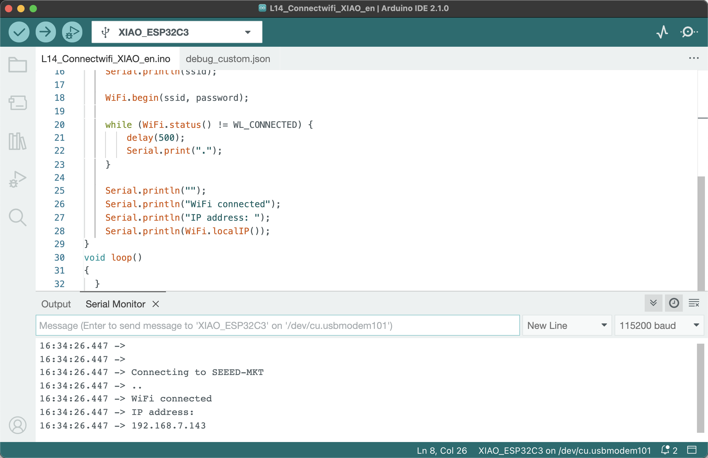
Connecting to a Wi-Fi Network
In this example, we will use the XIAO ESP32C3 to connect to your Wi-Fi network.
Step 1. Copy and paste the code below into the Arduino IDE.
#include <WiFi.h>

const char* ssid     = "your-ssid";
const char* password = "your-password";

void setup()
{
    Serial.begin(115200);
    delay(10);

    // We start by connecting to a WiFi network

    Serial.println();
    Serial.println();
    Serial.print("Connecting to ");
    Serial.println(ssid);

    WiFi.begin(ssid, password);

    while (WiFi.status() != WL_CONNECTED) {
        delay(500);
        Serial.print(".");
    }

    Serial.println("");
    Serial.println("WiFi connected");
    Serial.println("IP address: ");
    Serial.println(WiFi.localIP());
}
void loop()
{
  }
Get this program from Github
https://github.com/mouseart/XIAO-Mastering-Arduino-and-TinyML/tree/main/code/L14_Connectwifi_XIAO_en
Then, replace your-ssid in the code with the name of your Wi-Fi network, and replace your-password in the code with the password for your Wi-Fi network.
Step 2. Upload the code and open the serial monitor to check whether the development board is connected to the Wi-Fi network, as shown in the figure below.
🎓 Learn more: You can read the Wiki documentation for more about using the XIAO ESP32C3.
3.4.3 Task 2: Ping a Specified Website
With the knowledge above, we can now learn how to use the XIAO ESP32C3 to ping a specified website.
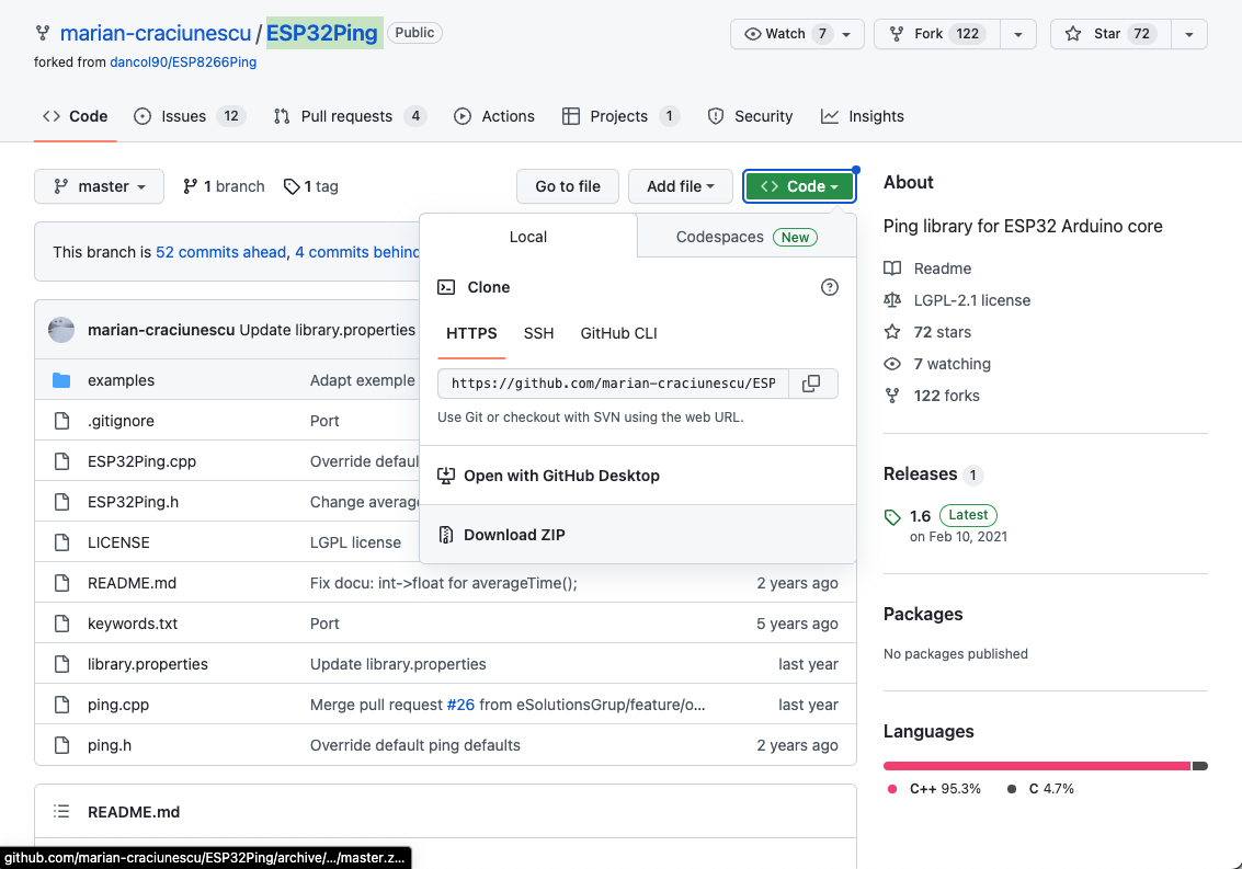
Step 1. Download and install the ESP32Ping library. Enter the URL 🔗 https://github.com/marian-craciunescu/ESP32Ping to go to the GitHub page, click on Code→Download ZIP to download the resource pack to your local machine, as shown in the figure below.
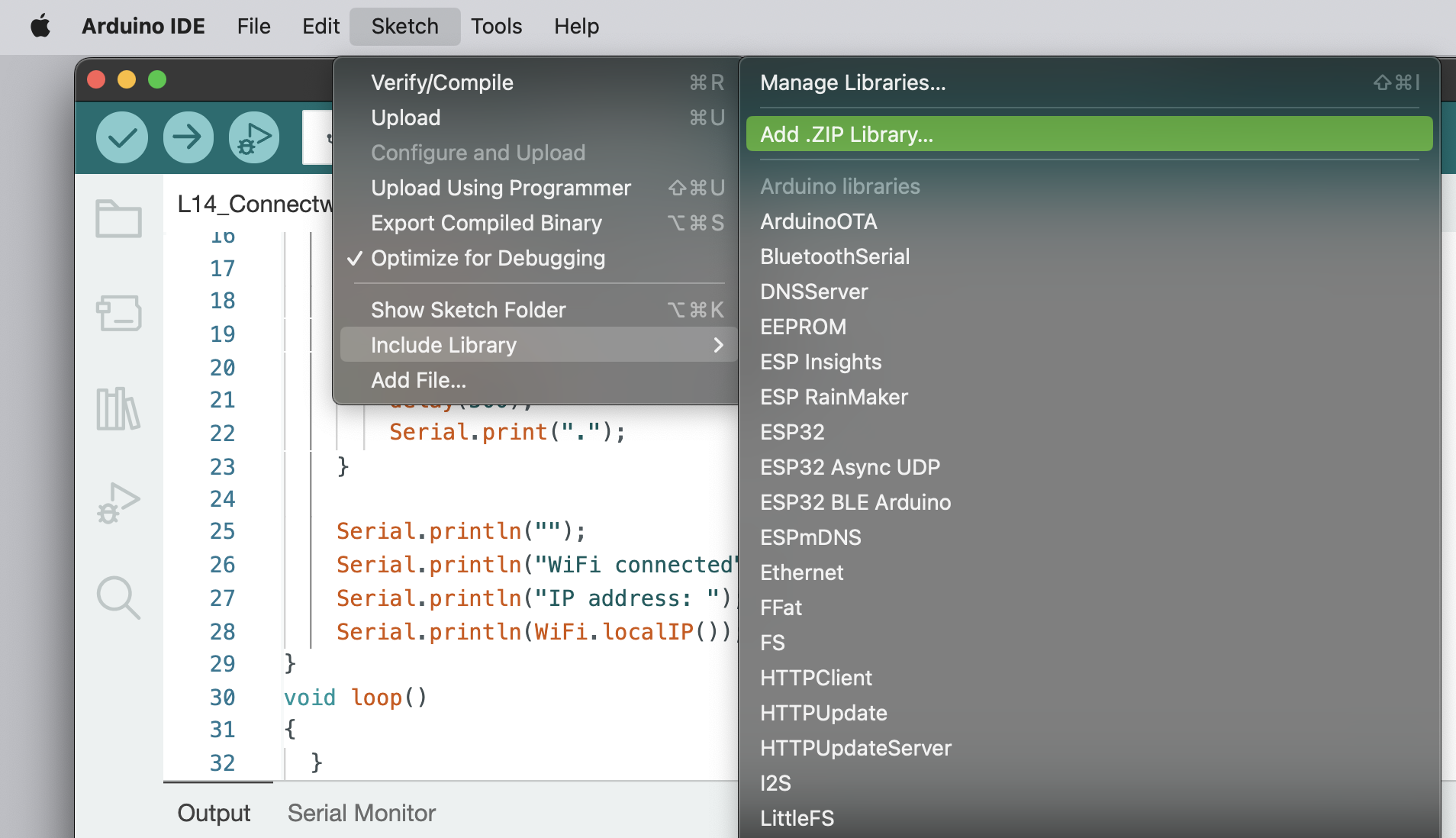
After downloading, open the Arduino IDE, click on Sketch→Include Library→Add .ZIP Library, and choose the ZIP file you just downloaded.
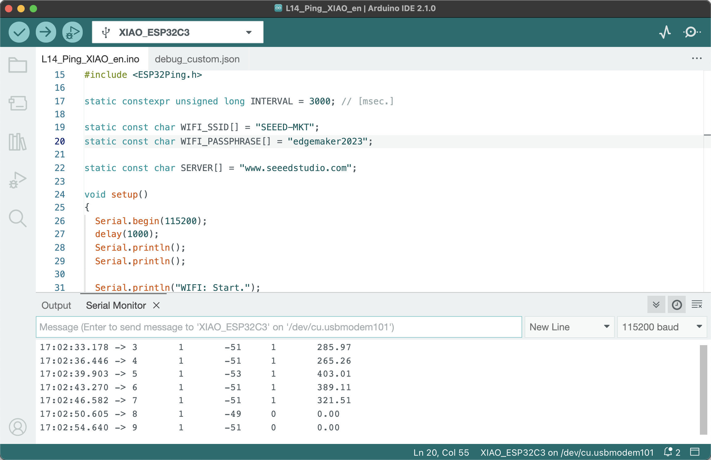
Step 2. Copy and paste the code below into the Arduino IDE. This code sets the test website to www.seeedstudio.com. Remember to replace your-ssid in the code with your Wi-Fi network name and your-password in the code with your Wi-Fi password.
////////////////////////////////////////////////////////////////////////////////
// IDE:
//   Arduino 2.0.3
// Platform:
//   esp32 2.0.4 - https://github.com/espressif/arduino-esp32
// Board:
//   XIAO_ESP32C3
// Libraries:
//   ESP32Ping 1.6 - https://github.com/marian-craciunescu/ESP32Ping

////////////////////////////////////////////////////////////////////////////////
// Includes

#include <WiFi.h>
#include <ESP32Ping.h>

static constexpr unsigned long INTERVAL = 3000; // [msec.]

static const char WIFI_SSID[] = "your-ssid";
static const char WIFI_PASSPHRASE[] = "your-password";

static const char SERVER[] = "www.google.com";

void setup()
{
    Serial.begin(115200);
    delay(1000);
    Serial.println();
    Serial.println();

    Serial.println("WIFI: Start.");
    WiFi.mode(WIFI_STA);
    if (WIFI_SSID[0] != '\0')
    {
        WiFi.begin(WIFI_SSID, WIFI_PASSPHRASE);
    }
    else
    {
        WiFi.begin();
    }
}

void loop()
{
    static int count = 0;

    const bool wifiStatus = WiFi.status() == WL_CONNECTED;
    const int wifiRssi = WiFi.RSSI();

    const bool pingResult = !wifiStatus ? false : Ping.ping(SERVER, 1);
    const float pingTime = !pingResult ? 0.f : Ping.averageTime();

    Serial.print(count);
    Serial.print('\t');
    Serial.print(wifiStatus ? 1 : 0);
    Serial.print('\t');
    Serial.print(wifiRssi);
    Serial.print('\t');
    Serial.print(pingResult ? 1 : 0);
    Serial.print('\t');
    Serial.println(pingTime);
    count++;

    delay(INTERVAL);
}
Get this program from Github
https://github.com/mouseart/XIAO-Mastering-Arduino-and-TinyML/tree/main/code/L14_Ping_XIAO_en
Step 3. Upload the code and open the serial monitor to check the ping results, as shown in the figure below.
3.4.4 Project Creation: Using XIAO ESP32C3 to Make HTTP GET and HTTP POST Requests
3.4.4.1 Introduction to HTTP Protocol
HTTP stands for HyperText Transfer Protocol. It’s an application-layer protocol for distributed, collaborative, and hypermedia information systems. HTTP is the most widely used network transmission protocol on the Internet, and all WWW files must comply with this standard.
HTTP is designed for communication between Web browsers and Web servers, but it can also be used for other purposes. HTTP is a protocol that uses TCP/IP to transmit data (such as HTML files, image files, query results, etc.).
Despite its wide use, HTTP has significant security flaws, mainly its plain text data transmission and lack of message integrity checks. These are exactly the two most critical security aspects in emerging applications like online payment, online trading, Internet of Things, etc. Browsers like Google Chrome, Internet Explorer, and Firefox issue warnings about insecure connections when visiting websites with mixed content composed of encrypted and unencrypted content using HTTP.
3.4.4.2 Introduction to HTTPS Protocol
HTTPS stands for HyperText Transfer Protocol Secure. It’s a protocol for secure communication over a computer network. HTTPS communicates via HTTP but uses SSL/TLS to encrypt packets. The main purpose of HTTPS is to authenticate the website server’s identity and protect the privacy and integrity of the exchanged data.

3.4.4.3 HTTP Request Methods
According to the HTTP standard, HTTP requests can use multiple request methods.
HTTP1.0 defined three request methods: GET, POST, and HEAD.
HTTP1.1 added six new request methods: OPTIONS, PUT, PATCH, DELETE, TRACE, and CONNECT.
| No. | Method | Description |
|---|---|---|
| 1 | GET | Requests specified page information and returns the entity body. |
| 2 | HEAD | Similar to a GET request, but the response returned doesn’t contain specific content, used to obtain headers. |
| 3 | POST | Submits data for processing to a specified resource (e.g., submits a form or uploads a file). The data is included in the request body. POST requests may result in the creation of a new resource and/or the modification of an existing resource. |
| 4 | PUT | The data sent from the client to the server replaces the content of a specified document. |
| 5 | DELETE | Requests the server to delete a specified page. |
| 6 | CONNECT | Reserved in HTTP/1.1 for proxy servers that can switch the connection to a pipe mode. |
| 7 | OPTIONS | Allows the client to view the server’s capabilities. |
| 8 | TRACE | Echoes the request received by the server, mainly used for testing or diagnosis. |
| 9 | PATCH | It’s a supplement to the PUT method, used to partially update a known resource. |
We’ve already learned how to connect to a Wi-Fi network using XIAO ESP32C3. Now, let’s try some more complex operations based on the network. The following sections will introduce how to use XIAO ESP32C3 to send HTTP GET and HTTP POST requests.
3.4.4.4 Task 3: Using XIAO ESP32C3 to Send an HTTP GET Request
To send an HTTP GET request, a corresponding backend server that supports the request is required. For convenient testing, we can set up a backend server on our own PC, allowing XIAO ESP32C3 to send an HTTP GET request to the PC through the local Wi-Fi connection.
There are many ways to set up a backend service. In this case, we’ll use the popular Python web framework — FastAPI to set up the backend server. To learn more about this tool, visit its official documentation.
Setting Up a Backend Server with FastAPI
Here is the Python server code.
from typing import Union
from pydantic import BaseModel
from fastapi import FastAPI
import datetime

app = FastAPI()
items = {}

class Sensor_Item(BaseModel):
    name: str
    value: float

@app.on_event("startup")
async def startup_event():
    items["sensor"] = {"name": "Sensor","Value":0}

@app.get("/items/{item_id}")
async def read_items(item_id: str):

    return items[item_id],datetime.datetime.now()

@app.post("/sensor/")
async def update_sensor(si: Sensor_Item):
    items["sensor"]["Value"] = si.value
    return si

@app.get("/")
def read_root():
    return {"Hello": "World"}
This code snippet, implemented using the Python FastAPI framework, can return the latest information of the Sensor stored on the backend server when we use a get request on http://domain/items/sensor. When we use post to send data to http://domain/sensor/, it can modify and record the latest Sensor value. The operation steps are as follows:
Step 1. Create a python file named main.py locally, copy and paste the code above into main.py. Then, on your PC, open the terminal and execute the following commands to install FastAPI.
pip install fastapi
pip install "uvicorn[standard]"
Step 2. Execute the following command to start the backend service and local monitoring.
uvicorn main:app --reload --host 0.0.0.0⚠️ Note:
When running the command above, make sure the terminal is currently in the directory wheremain:appresides. If there is a prompt during running:
ERROR: [Errno 48] Address already in useThis means the current address is already occupied and there is an address conflict. You can specify a specific port as shown in the command below.
uvicorn main:app --reload --host 0.0.0.0 --port 1234If the [Errno 48] error still appears, you can modify the port number after port.
The prompt information after the command is successfully run is as follows
INFO:     Will watch for changes in these directories: ['']
INFO:     Uvicorn running on http://0.0.0.0:1234 (Press CTRL+C to quit)
INFO:     Started reloader process [53850] using WatchFiles
INFO:     Started server process [53852]
INFO:     Waiting for application startup.
INFO:     Application startup complete.
The backend server for testing is now running normally.
Using XIAO ESP32C3 to Send an HTTP GET Request
Next, we’ll perform a request test on XIAO ESP32C3.
The GET method should only be used for reading data, and should not be used in operations that generate “side effects”. GET requests directly issued by browsers can only be triggered by a URL. If you want to carry some parameters outside of the URL in GET, you can only rely on the querystring (query string) attached to the URL.
Step 1: Copy and paste the following code into the Arduino IDE. This code sets the tested serverName to http://192.168.1.2/items/sensor. The 192.168.1.2 needs to be replaced with the IP address of your PC acting as the backend server. To get the IP address of your PC, Windows users can enter the ipconfig command in the command line window, and Mac users can enter the ifconfig command in the terminal window. Remember to change your-ssid in the code to your Wi-Fi network name and your-password to the corresponding Wi-Fi password.
#include "WiFi.h"
#include <HTTPClient.h>

const char* ssid = "your-ssid";
const char* password = "your-password";
String serverName = "http://192.168.1.2/items/sensor";
unsigned long lastTime = 0;
unsigned long timerDelay = 5000;

void setup()
{
    Serial.begin(115200);

    WiFi.begin(ssid, password);
    Serial.println("Connecting");
    while(WiFi.status() != WL_CONNECTED) {
        delay(500);
        Serial.print(".");
    }
    Serial.println("");
    Serial.print("Connected to WiFi network with IP Address: ");
    Serial.println(WiFi.localIP());

    Serial.println("Timer set to 5 seconds (timerDelay variable), it will take 5 seconds before publishing the first reading.");

    Serial.println("Setup done");
}

void loop()
{
    if ((millis() - lastTime) > timerDelay) {
        //Check WiFi connection status
        if(WiFi.status()== WL_CONNECTED){
            HTTPClient http;

            String serverPath = serverName ;

            http.begin(serverPath.c_str());

            int httpResponseCode = http.GET();

            if (httpResponseCode>0) {
                Serial.print("HTTP Response code: ");
                Serial.println(httpResponseCode);
                String payload = http.getString();
                Serial.println(payload);
            }
            else {
                Serial.print("Error code: ");
                Serial.println(httpResponseCode);
            }

            http.end();
        }
        else {
            Serial.println("WiFi Disconnected");
        }
        lastTime = millis();
    }
}
Get this program from Github
https://github.com/mouseart/XIAO-Mastering-Arduino-and-TinyML/tree/main/code/L14_HTTPget_XIAO_en
⚠️ Note:
We need to change theserverNamein the Arduino code to the IP address of the host running the backend service. The XIAO ESP32C3 needs to be on the same local area network as it. If the local area network IP of the backend server (in this example, your PC) is192.168.1.2, then the GET request interface ishttp://192.168.1.2/items/sensor, and other interfaces are similar. If you specified a port when running the backend service and local monitoring, the GET request interface would behttp://192.168.1.2:1234/items/sensor.
Step 2: Upload the code to XIAO ESP32C3 in the Arduino IDE. After the upload is successful, open the serial monitor to check the result returned by our backend server after the GET is issued, as shown in the figure below.
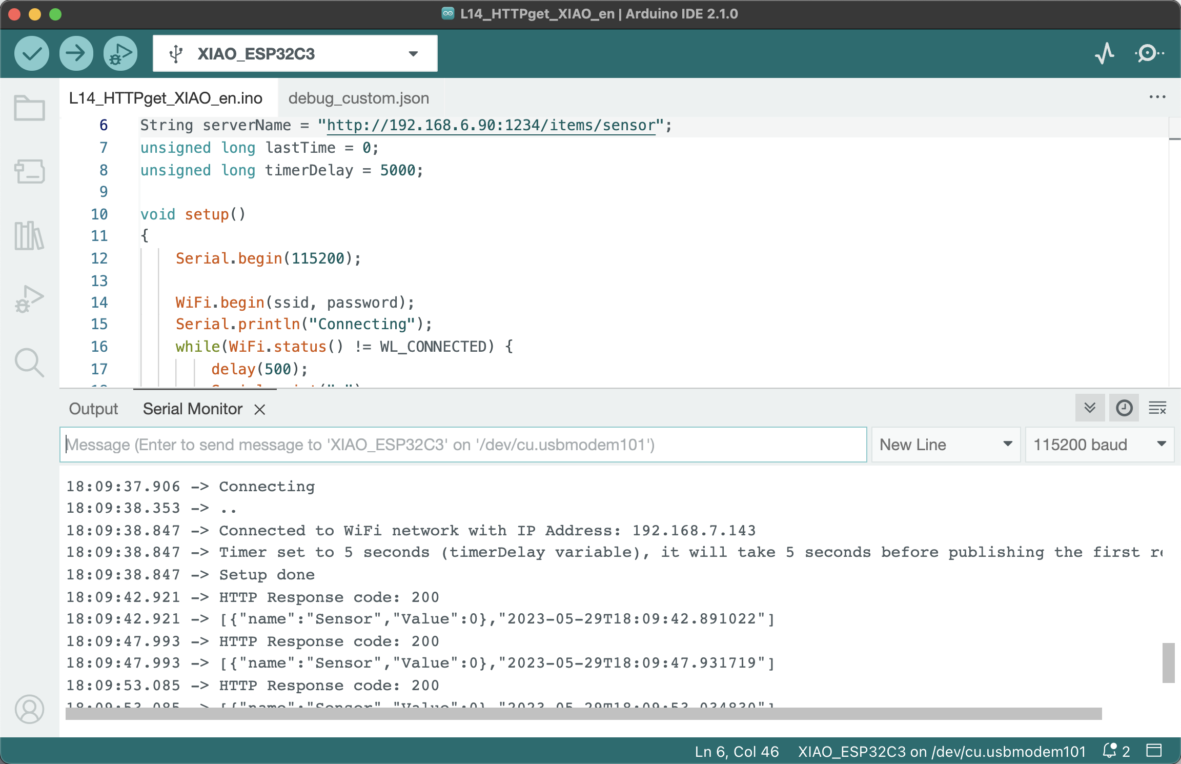
The prompt HTTP Response code: 200 means the request has been successful, and our XIAO ESP32C3 has successfully gotten data from the server.
3.4.4.5 Task 4: Using XIAO ESP32C3 to Send an HTTP POST Request
Submit data to a specified resource and request the server to process it (for example, submit a form or upload a file). The data is included in the request body. This request may create new resources or modify existing resources, or both. Each time it is submitted, the form data is encoded into the body of the HTTP request by the browser. The body of a POST request issued by a browser mainly has two formats, one is application/x-www-form-urlencoded used to transmit simple data, roughly in the format of key1=value1&key2=value2. The other is for transmitting files and will use the multipart/form-data format. The latter is adopted because the encoding method of application/x-www-form-urlencoded is very inefficient for binary data like files.
Next, we will submit experimental data to the backend server built on our machine in a manner similar to submitting a form, and verify whether the backend server has received the data.
Step 1: Before starting this example, make sure that the backend server built with FastAPI in the previous step is running normally. If not, please refer to the above instructions to start the server program.
Step 2: Copy and paste the following code into the Arduino IDE. This code sets the tested serverName to http://192.168.1.2/sensor/. The 192.168.1.2 needs to be replaced with the IP address of your PC acting as the backend server. Remember to change your-ssid in the code to your Wi-Fi network name and your-password to the corresponding Wi-Fi password.
#include <WiFi.h>
#include <HTTPClient.h>

const char* ssid = "your-ssid";
const char* password = "your-password";

const char* serverName = "https://192.168.1.2/sensor/";

unsigned long lastTime = 0;
unsigned long timerDelay = 5000;

void setup() {
  Serial.begin(115200);

  WiFi.begin(ssid, password);
  Serial.println("Connecting");
  while(WiFi.status() != WL_CONNECTED) {
    delay(500);
    Serial.print(".");
  }
  Serial.println("");
  Serial.print("Connected to WiFi network with IP Address: ");
  Serial.println(WiFi.localIP());

  Serial.println("Timer set to 5 seconds (timerDelay variable), it will take 5 seconds before publishing the first reading.");
}

void loop() {
  //Send an HTTP POST request every 10 minutes
  if ((millis() - lastTime) > timerDelay) {
    //Check WiFi connection status
    if(WiFi.status()== WL_CONNECTED){
      WiFiClient client;
      HTTPClient http;


      http.begin(client, serverName);

      http.addHeader("Content-Type", "application/json");
      int httpResponseCode = http.POST("{\"name\":\"sensor\",\"value\":\"123\"}");

      Serial.print("HTTP Response code: ");
      Serial.println(httpResponseCode);

      // Free resources
      http.end();
    }
    else {
      Serial.println("WiFi Disconnected");
    }
    lastTime = millis();
  }
}
Get this program from Github
https://github.com/mouseart/XIAO-Mastering-Arduino-and-TinyML/tree/main/code/L14_HTTPpost_XIAO_en
Step 2: Upload the code to XIAO ESP32C3 using the Arduino IDE. After a successful upload, open the Serial Monitor to examine the result returned by our backend server in response to the GET request. The image below illustrates the process.
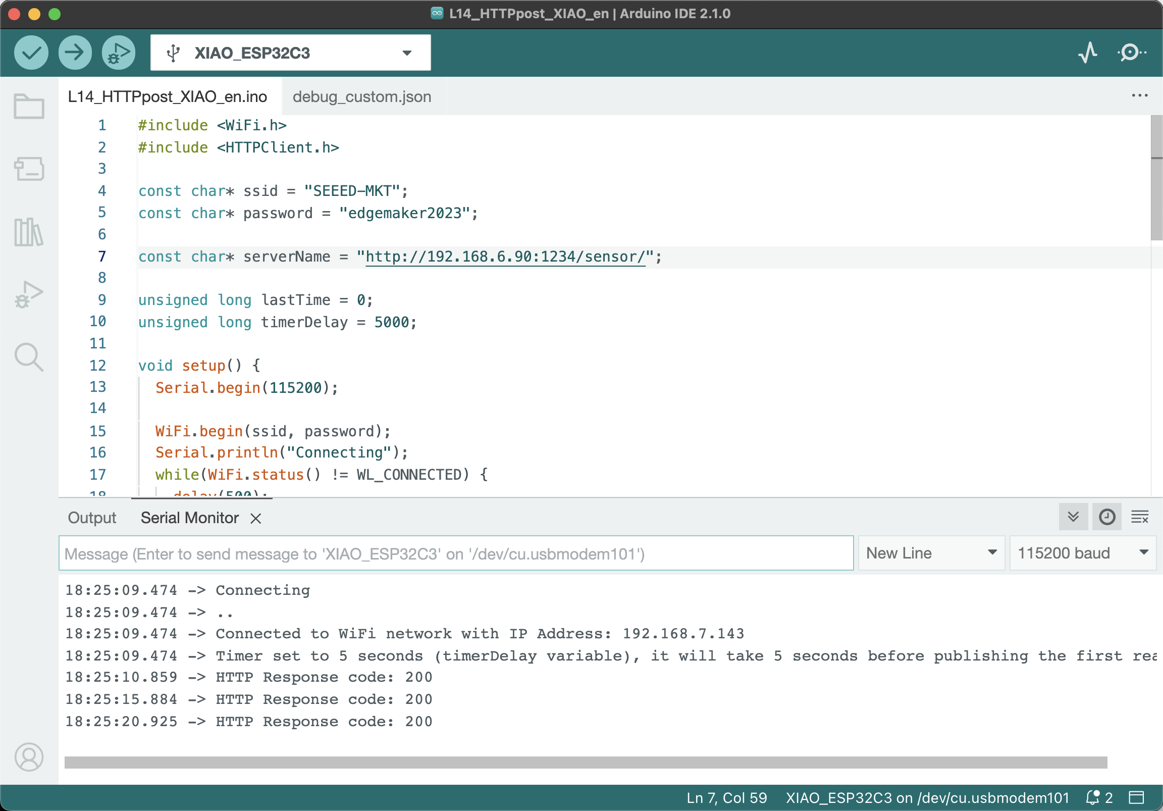
The message **HTTP Response code: 200** signifies a successful request. On your local PC, open a browser and navigate to **http://192.168.1.2/items/sensor** (please replace the IP address according to your actual PC’s IP address, and if a port has been set, append a colon followed by the designated port number after the IP address). You should now see the most recent data sent by the XIAO ESP32C3. Since XIAO sends data every 5 seconds, you can always view the most recent data received by the backend server by refreshing the current page (the timestamp of the data will change).
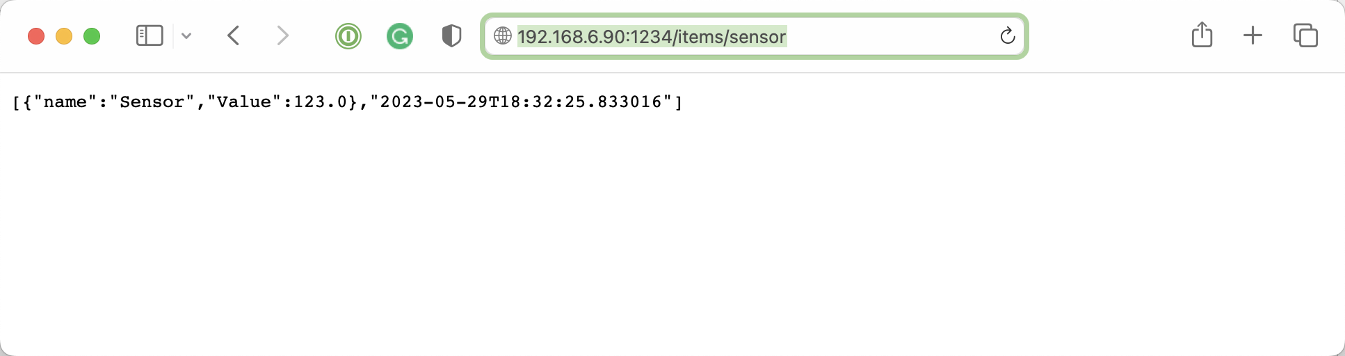
We have now successfully sent data from XIAO ESP32C3 to the local backend server.