1.4 Monitor Knob Value Changes with Serial Monitor
When we write a few lines of code to control the board to light up the LED, or to use a button switch to control the buzzer, we can intuitively see the working state of these external hardware. If it achieves our expected results, it is very fortunate. What if it doesn’t? The program compiles without error, where is the mistake? It would be nice if they could speak up. In this section, we will learn how to communicate with the computer through the serial monitor and check the running status and information of the program and hardware.
1.4.1 Background Knowledge
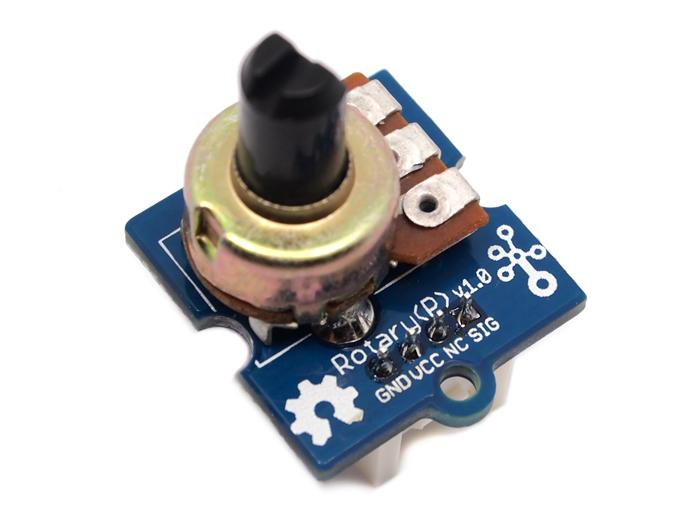
1.4.1.1 Rotary Potentiometer
The rotary potentiometer, although it doesn’t seem common, has a very wide range of uses in household appliances and industrial equipment. For example, the volume knob on the sound system.

The rotary potentiometer can produce an analog output value between 0 and VCC (the voltage of the connected circuit) on its connected pins. By rotating the knob, you can change the output voltage value. The range of the knob’s angle is 300°, and the output value is 0-1023. We can use the rotary potentiometer to control the LED light to show brightness changes, or control the servo to rotate at different angles, etc.
1.4.1.2 Analog I/O
In the Arduino series of development boards, the pins with “A” in front of the pin number are analog input pins. We can read the analog value on these pins to achieve the effect we want.
Analog Signal
In life, analog signals are everywhere, such as the change in sound, light, temperature, etc., the frequency, amplitude, etc. of the signal can change continuously with time.
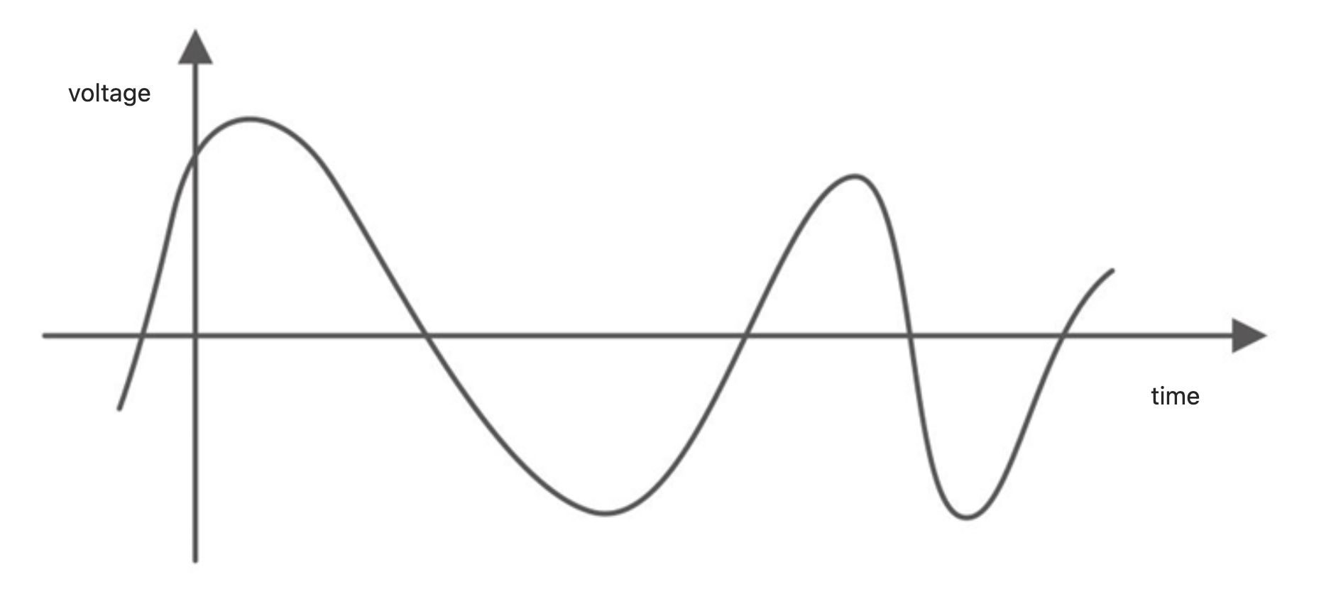
So how do we read the analog value of the pin through the development board? The analog input pin has an ADC (analog-to-digital converter), which can convert the external input analog signal into a digital signal that the development board can recognize, thereby achieving the function of reading in analog values, i.e., it can convert a 0-5V voltage signal into an integer value of 0-1023.
analogRead();
Read the value from the specified analog pin.
Syntax
analogRead(pin);
Parameters
pin:The name of the analog input pin to be read.
analogWrite();
Corresponding to analog input is analog output. We use the analogWrite() function to achieve this function. It should be noted that when using this function, it is only through a special way to output different voltages to achieve the effect of approximate analog values. This method is called PWM pulse width modulation, so we are writing PWM square waves to the specified pin, not the true analog value.
Syntax
analogWrite(pin, value);
Parameters
pin:The pin to output PWM, allowed data type: int.
value: Duty cycle, between 0-255, allowed data type: int.
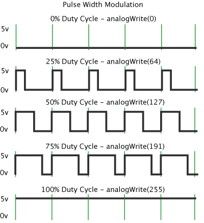
PWM Pulse Width Modulation
Pulse width modulation (PWM) is a way to achieve analog results through digital output. Simply put, you can control the charging current by adjusting the period of PWM and the duty cycle of PWM. As shown in the figure, the voltage is switched back and forth between 0V (low level) and 5V (high level). A switchback is a period. In this period, if the time of high voltage is 25% and the time of low voltage is 75%, the duty cycle is 25%, and the output voltage is 5V.
When we write a few lines of code to control the lighting of LEDs on the development board, or use button switches to control the buzzer, we can directly observe the working status of these external hardware. If it achieves our expected results, we are lucky. But what if it doesn’t? The program compiles without errors, so where is the problem? It would be nice if they could talk. In this section, we will learn how to communicate with the computer, monitor the running status and information of the program and hardware through the serial monitor.
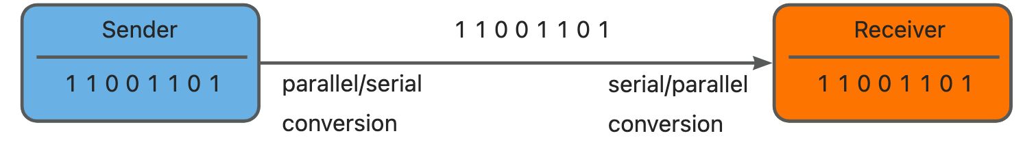
1.4.1.3 Serial Communication
When we want to communicate with other devices using XIAO, the most common method is serial communication. All Arduino series development boards have this functionality. As we know, computers understand binary data (like 1010). Therefore, among electronic devices, serial communication achieves its function by sending and receiving such data. The key component to implement this function is the USART (Universal Synchronous/Asynchronous Receiver Transmitter). In the Arduino IDE, we can observe the sent and received data through the Serial Monitor, and we need related serial communication functions to implement this feature.
**Serial.begin();**
This function is used to open the serial port and set the data transmission rate.
Syntax
Serial.begin(speed);
Parameters
Serial: Serial port object.
speed: Baud rate, commonly set to values like 9600, 115200, etc.
**Serial.println();**
Syntax
Serial.println(val);
Parameters
Serial: Serial port object.
val: The value to be printed, which can be of any data type.
For example, to print “hello world!!!” to the Serial Monitor, we need to initialize the serial port in the setup() function and output “hello world!!!” through the serial port in the loop() function:
void setup() {
    Serial.begin(9600); // Initialize the serial port and set the data transmission rate to 9600
}
void loop() {
    Serial.println("hello world!!!"); // Output "hello world!!!" through the serial port
}
Returning to the question at the beginning of this section: when we have written the code and verified it to be correct, but the effect of running the code exceeds expectations or the hardware doesn’t respond at all, where is the problem? At this time, we can use the Serial Monitor to observe the data sent or received by the hardware to make a judgment. For instance, we can control the on-off state of an LED with a button, and we can use the Serial Monitor to check the returned value when the button is pressed to determine whether the button is working properly. Next, we will learn how to use the Serial Monitor to make the hardware “speak”.
1.4.2 Task 1: Use the Serial Monitor to Check if the Button is Pressed
Analysis
Remember controlling the on-off state of an LED with a button? Some of the code can be reused. We only need to read the button on-off setting and button on-off state code, and then add the initialization of the serial port and the data sent to the serial port. The program writing still follows three steps:
- Define button pins and variables.
- Initialize the serial port, set the serial port baud rate, and set the status of the button on-off pin.
- Read the button state and send it to the serial port.
Write the program
Step 1: Define the button pin and variable.
const int buttonPin = 1; // Define the button switch as pin 1. If you are using XIAO RP2040/XIAO ESP32, please change 1 to D1
int buttonState = 0; // Define buttonState as a variable to store the button status
Step 2: Initialize the serial port, set the baud rate of the serial port, and set the button switch pin status.
void setup() {
    pinMode(buttonPin, INPUT_PULLUP);  // Set the button pin as input
    Serial.begin(9600); // Initialize the serial port
}
Step 3: Read the button status and send it to the serial port
void loop() {
    buttonState = digitalRead(buttonPin);  // Read the button status and store it in the buttonState variable
    Serial.println(buttonState); // Send the button status data to the serial port
    delay(500);
}
Get this program from Github
https://github.com/mouseart/XIAO-Mastering-Arduino-and-TinyML/tree/main/code/L4_ReadButton_XIAO_en
Upload the program:
We will upload the written program to the hardware. First, connect the XIAO to the computer with the data cable from the kit.
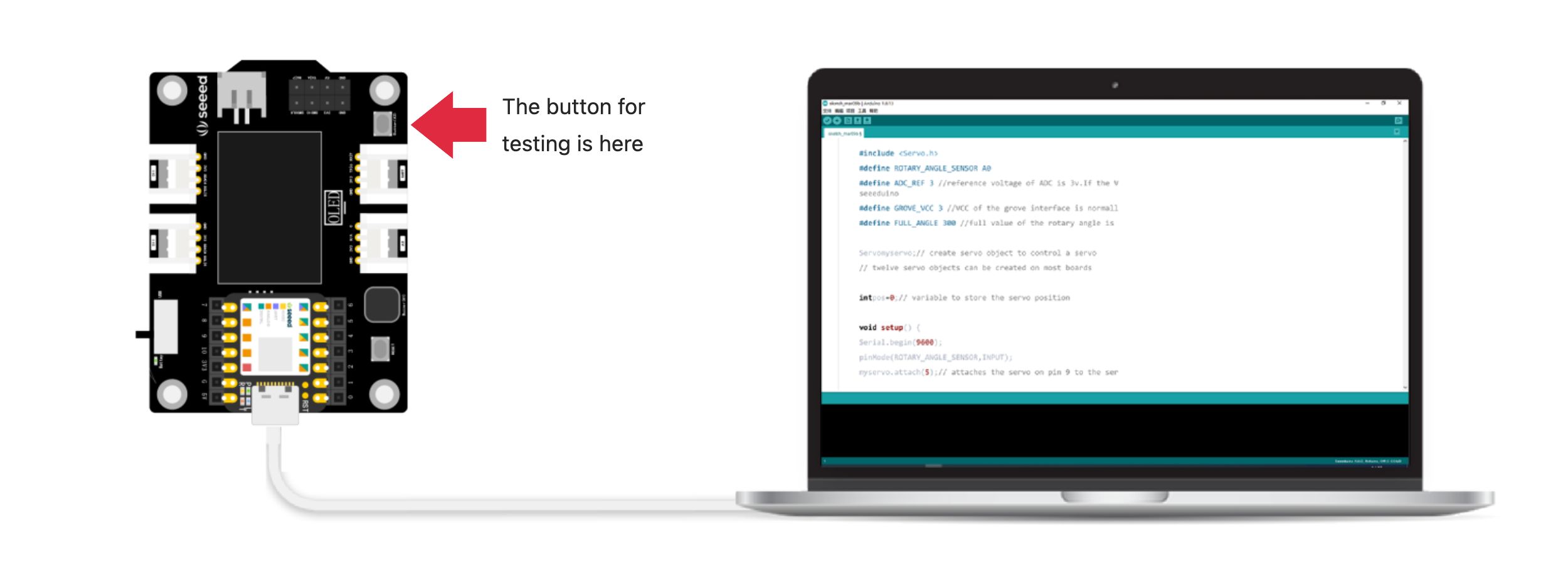
Note the position of the buttons on the XIAO extensions used for testing in the figure.
Click ![]() (Verify Button) in the Arduino IDE to verify the program. If the verification is correct, click
(Verify Button) in the Arduino IDE to verify the program. If the verification is correct, click ![]() (Upload Button) to upload the program to XIAO. When the debug area shows “Done uploading.”, open the serial monitor and observe the value changes printed by the serial monitor when the button is pressed and released. What did you find?
(Upload Button) to upload the program to XIAO. When the debug area shows “Done uploading.”, open the serial monitor and observe the value changes printed by the serial monitor when the button is pressed and released. What did you find?
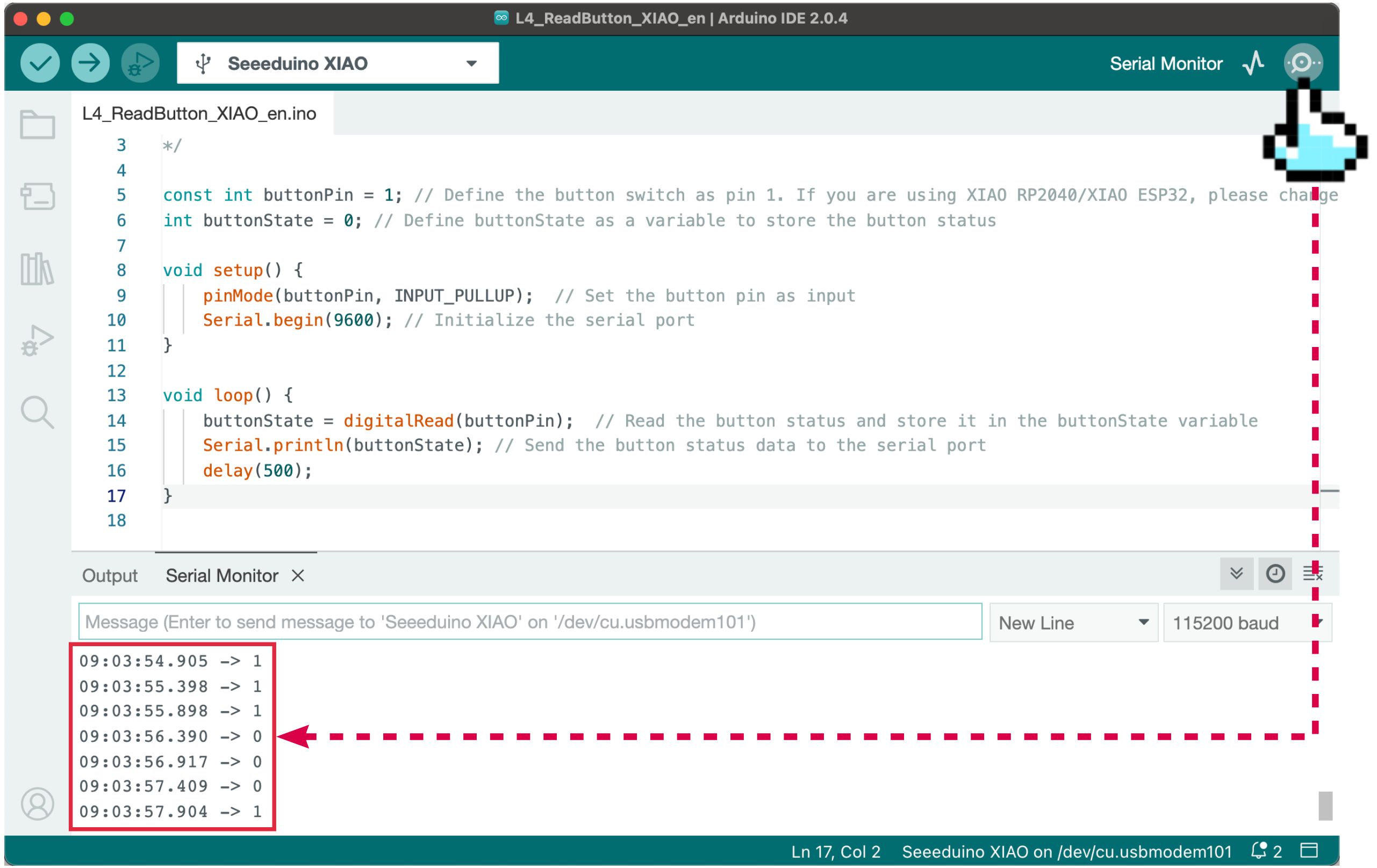
When we press the button on the XIAO expansion board, the serial monitor shows 0, and when we release the button, the serial monitor shows 1.
1.4.3 Task 2: Using the Serial Monitor to View Knob Value Changes
Analysis:
In Task 1, the button switch is a digital input that sends out digital signals 0 and 1, while the knob potentiometer returns an analog signal. We need to read the rotation angle value of the knob potentiometer on pin A0 and send it to the serial port. The program also consists of three steps:
- Define the knob potentiometer pin and variables.
- Initialize the serial port and set the status of the knob potentiometer pin.
- Read and calculate the rotation angle value of the knob potentiometer and send it to the serial port.
Write the program
Step 1: Define the knob potentiometer pin and variables. Here we need to define the voltage value of the ADC (Analog-to-Digital Converter) and the reference voltage of the Grove module interface, because we will calculate the voltage changes in the circuit where the knob switch is connected through these voltage values.
#define ROTARY_ANGLE_SENSOR A0  // Define the rotary potentiometer interface A0
#define ADC_REF 3 // ADC reference voltage is 3V
#define GROVE_VCC 3 // Grove interface reference voltage is 3V
#define FULL_ANGLE 300 // The maximum rotation angle of the knob potentiometer is 300°
Step 2: Initialize the serial port, set the baud rate of the serial port, and set the status of the knob potentiometer pin.
void setup()
{
    Serial.begin(9600);//Initialize the serial port
    pinMode(ROTARY_ANGLE_SENSOR, INPUT);//Set the rotary potentiometer pin to input state
}
Step 3: Read and calculate the rotational angle value of the rotary potentiometer and send it to the serial port. Here, we first need to set the data type of the voltage variable, set the analog value variable of the rotary potentiometer pin, and then calculate the real-time voltage. After calculating the real-time voltage, calculate the rotational angle value of the rotary potentiometer.
void loop()
{
    float voltage;    //Variable voltage is of floating-point type
    int sensorValue = analogRead(ROTARY_ANGLE_SENSOR);    //Read the analog value at the rotary potentiometer pin
    voltage = (float)sensorValue*ADC_REF/1023;    //Calculate real-time voltage
    float degrees = (voltage*FULL_ANGLE)/GROVE_VCC;    //Calculate the rotation angle of the knob
    Serial.println("The angle between the mark and the starting position:");    //Print characters at the serial port
    Serial.println(degrees);    //Print the rotation angle value of the rotary potentiometer at the serial port
    delay(100);
}
#defineMacro Definition
#defineis a pre-processing command used for macro definitions. In Arduino, we can use#defineto name constants. During the compilation of the program, all occurrences of the “macro name” will be replaced with the string in the macro definition, such as#define ledPin 5. During compilation, 5 will replace all uses ofledPin. Syntax:#define constant name constant value. The “#” symbol is mandatory, and there is no need to use the “;” symbol at the end of the sentence.
The complete code is as follows:
/*
 * Use the serial monitor to view the knob potentiometer
 */
#define ROTARY_ANGLE_SENSOR A0//Define the rotary potentiometer interface A0
#define ADC_REF 3 //ADC reference voltage 3V
#define GROVE_VCC 3 //Reference voltage 3V
#define FULL_ANGLE 300 //The maximum rotation angle of the rotary potentiometer is 300°

void setup()
{
    Serial.begin(9600);//Initialize the serial port
    pinMode(ROTARY_ANGLE_SENSOR, INPUT);//Set the rotary potentiometer pin as an input
}

void loop()
{
    float voltage;//Variable voltage is of floating-point type
    int sensorValue = analogRead(ROTARY_ANGLE_SENSOR);//Read the analog value at the rotary potentiometer pin
    voltage = (float)sensorValue*ADC_REF/1023;//Calculate real-time voltage
    float degrees = (voltage*FULL_ANGLE)/GROVE_VCC;//Calculate the rotation angle of the knob
    Serial.println("The angle between the mark and the starting position:");//Print characters at the serial port
    Serial.println(degrees);//Print the rotation angle value of the rotary potentiometer at the serial port
    delay(100);
}
Get this program from Github https://github.com/mouseart/XIAO-Mastering-Arduino-and-TinyML/tree/main/code/L4_ReadRotary_XIAO_en
Upload the program:
After writing the program, since external sensors are used, connect the knob module to the A0 interface using the four-color Grove cable as shown in the image below:
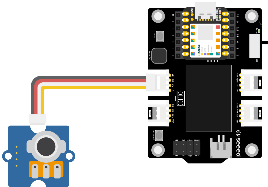
After connecting, connect the XIAO main control board to your computer using a data cable.
In the Arduino IDE, click on the verification button ![]() to verify the program. If it verifies correctly, click the upload button to upload the program to
to verify the program. If it verifies correctly, click the upload button to upload the program to ![]() the hardware. When the debugging area shows “Done uploading.”, you can proceed. Open the serial monitor and rotate the knob potentiometer to observe the data changes displayed in the serial monitor. These changes represent the angle value of the knob.
the hardware. When the debugging area shows “Done uploading.”, you can proceed. Open the serial monitor and rotate the knob potentiometer to observe the data changes displayed in the serial monitor. These changes represent the angle value of the knob.
1.4.4 Extended Exercise
While observing the angle value of the knob potentiometer in the serial monitor, we find that the value is constantly jumping and changing. Observing through the numbers alone is not very intuitive. At this time, we can use the serial plotter. With it, we can plot the data that is printed to the Arduino’s serial port in real time. Based on the second task, close the serial monitor and open the “Tools → Serial Plotter” as shown in the image below:
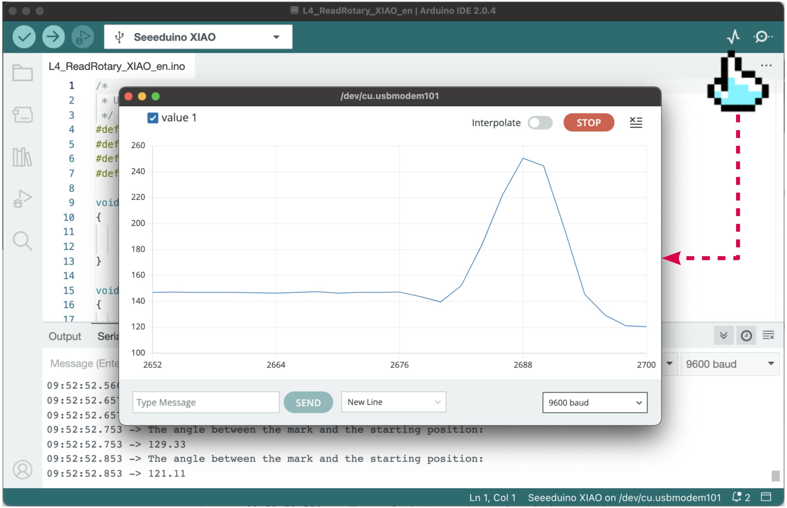
The serial plotter draws the data obtained from the serial port into an XY axis curve chart, where the X-axis represents the change in time and the Y-axis represents the data obtained from the serial port. Through the chart, you can more intuitively see the change in data. Please give it a try.