1.1 First Arduino program with Seeed Studio XIAO: Blink
Arduino is a globally popular open-source electronic prototyping platform, including various models of Arduino development boards and the Arduino IDE software platform. Because of its open, convenient, and easy-to-start characteristics, it has become the first choice for many software and hardware beginners.
With it, you can quickly complete project development and implement your ideas. To date, Arduino has introduced various models of controllers and numerous peripheral modules, such as sensors, actuators, expansion boards, etc. These modules can implement various exciting and practical projects when used with Arduino.
The Seeed Studio XIAO series products we are learning about today are development boards derived from Arduino. They belong to the Seeeduino series and are the smallest members of this series.
1.1.1 Arduino IDE Text Editor
We need to program the hardware through the Arduino IDE text editor. If you have not installed the Arduino IDE, go to the download page to install it: 🔗 Software. The Arduino IDE (Integrated Development Environment) is a programming software designed explicitly for Arduino. Through it, we can write and upload different programs for Arduino hardware. When we open the Arduino IDE software, it will create a new file named Sketch, which we can rename.
For Windows Users
The interface of the Arduino IDE is spotless, and can be divided into four parts: menu bar, toolbar, editing area, and debug window.
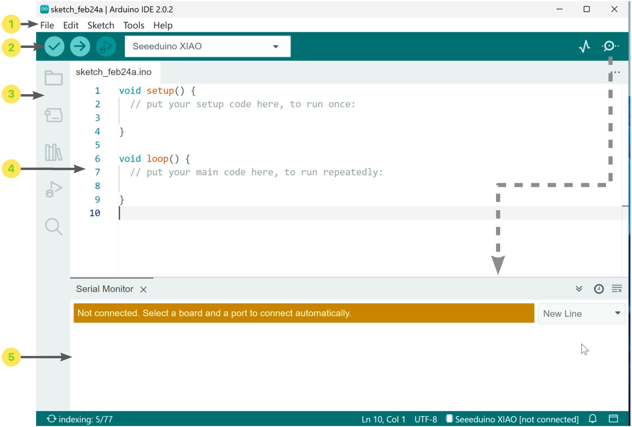
![]() Menu bar: Includes files, edit, sketch, tools, and help, such as new, save, example programs, select serial port, etc.
Menu bar: Includes files, edit, sketch, tools, and help, such as new, save, example programs, select serial port, etc.
![]() Horizontal toolbar: Contains several commonly used function buttons: verify, upload, debug, board selection, serial plotter, and serial monitor selection.
Horizontal toolbar: Contains several commonly used function buttons: verify, upload, debug, board selection, serial plotter, and serial monitor selection.
![]() Vertical toolbar: Contains shortcuts to the project folder, board manager, library manager, debug, and search.
Vertical toolbar: Contains shortcuts to the project folder, board manager, library manager, debug, and search.
![]() Code editing area: This is where you write program code, just as we usually type text in a Word window. Write the program code in this area.
Code editing area: This is where you write program code, just as we usually type text in a Word window. Write the program code in this area.
![]() Serial monitor, output window: On the right side of the horizontal toolbar, you can open or close the serial monitor window.
Serial monitor, output window: On the right side of the horizontal toolbar, you can open or close the serial monitor window.
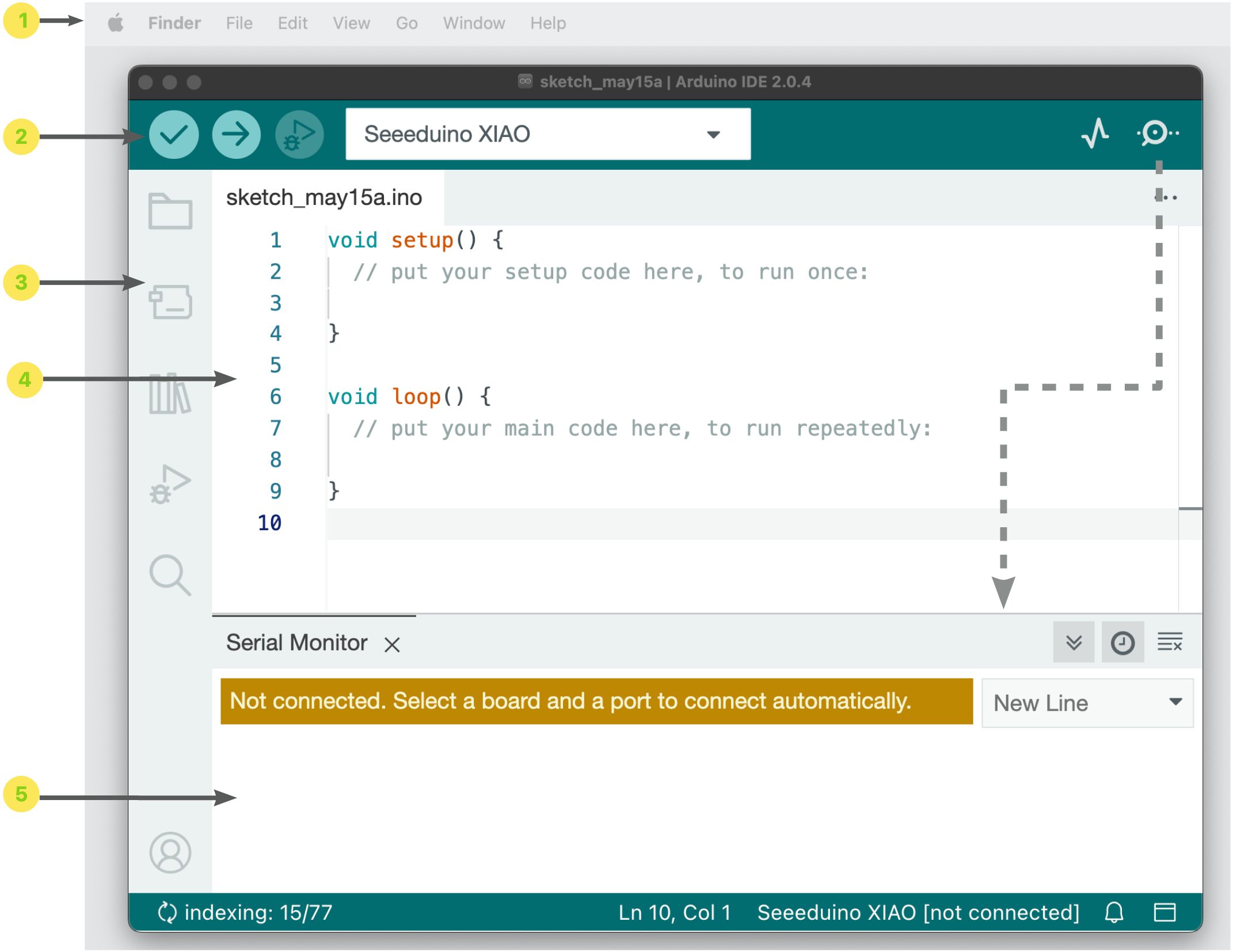
For MAC Users
Except for the location of the menu bar (at the top), which is slightly different from Windows users, all other tools and experiences are the same.
1.1.2 Adding Seeed Studio XIAO to Arduino IDE
⚠️ Attention
Due to space limitations, all parts of this course’s program code and hardware connection are based on Seeed Studio XIAO SAMD21. Most of the code in the book can be applied to all products in the Seeed Studio XIAO series. If there are exceptions, they will be additionally marked or explained for applicable hardware. If not marked, they apply to multiple products.
We must add the Seeed Studio XIAO series products to the Arduino IDE to start our learning journey.
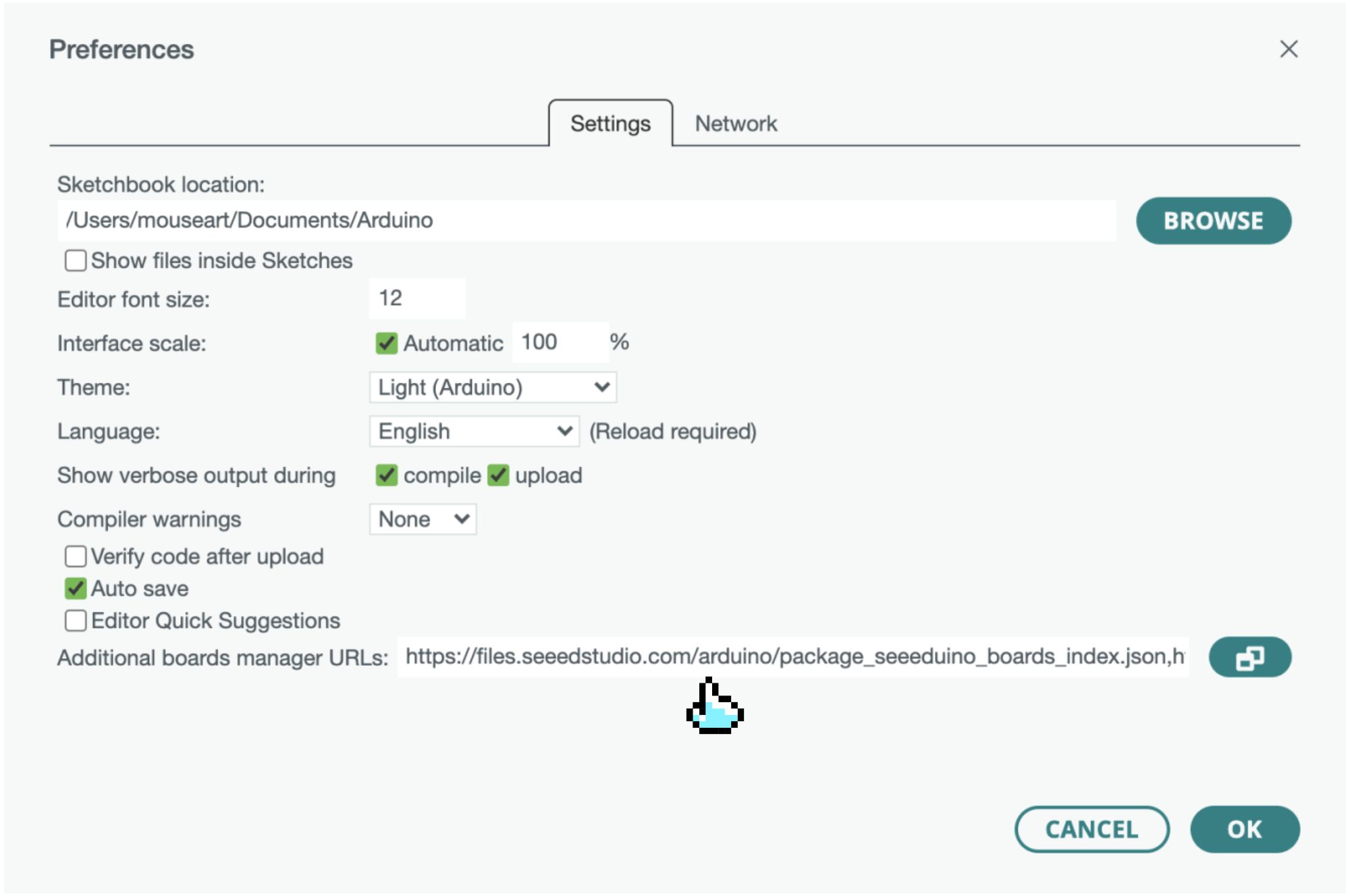
- For Windows users, first, open your Arduino IDE, click “File→Preferences” in the top menu bar, as shown in the figure, and copy the following URL into “Additional Boards Manager URLs.”
- For Mac users, first, open your Arduino IDE, click “Arduino IDE→Preferences” in the top menu bar, as shown in the figure, and copy the following URL into “Additional Boards Manager URLs.”
- For Seeed Studio XIAO SAMD21, XIAO nRF52840, and XIAO nRF52840 Sense, copy the link address below: https://files.seeedstudio.com/arduino/package_seeeduino_boards_index.json
- For Seeed Studio XIAO RP2040, copy the link address below: https://github.com/earlephilhower/arduino-pico/releases/download/global/package_rp2040_index.json
- For Seeed Studio XIAO ESP32C3, XIAO ESP32S3, copy the link address below: https://raw.githubusercontent.com/espressif/arduino-esp32/gh-pages/package_esp32_dev_index.json
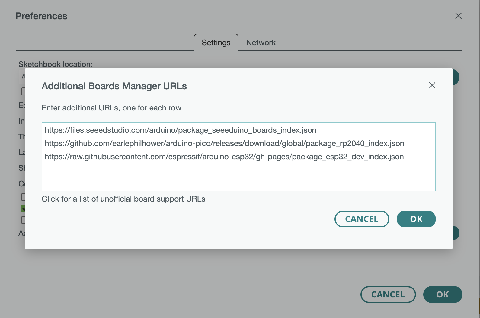
If you frequently use multiple different models of XIAO at the same time, you can click on the![]() icon on the right side of the address bar and add all three addresses above to the board manager, as shown in the figure below.
icon on the right side of the address bar and add all three addresses above to the board manager, as shown in the figure below.
Next, click “Tools→Board→Board Manager,” enter the keyword Seeeduino XIAO in the search bar, find Seeed SAMD Boards in the appeared entries, and click INSTALL.
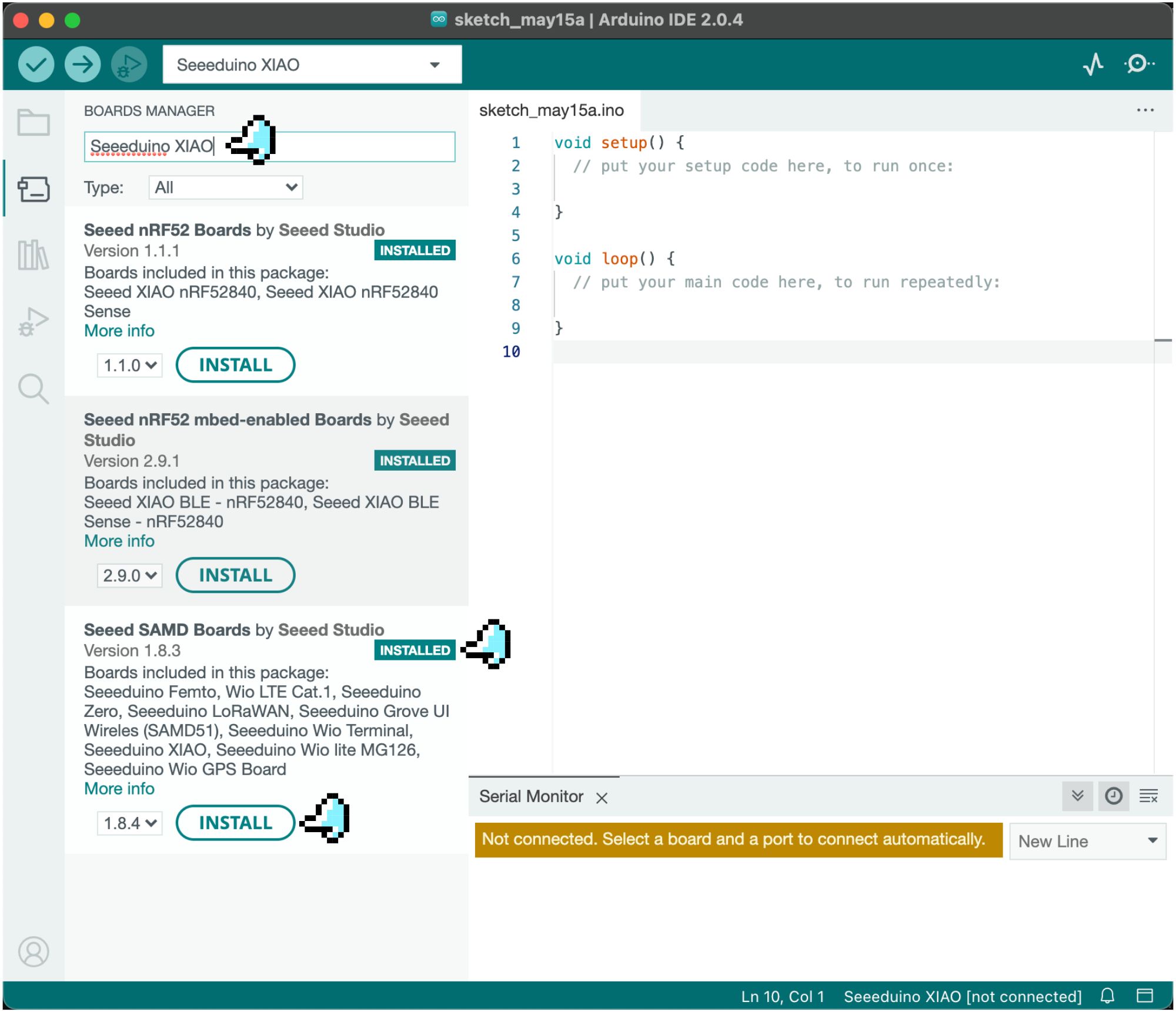
When the installation starts, you will see an output pop-up window. After the installation is complete, an “INSTALLED” option will appear.
⚠️ Attention
- Enter “RP2040” in the search bar to find the installation package for Seeed XIAO RP2040.
- Enter “XIAO nrf52840” to find two installation packages: Seeed nRF52 Boards (for low-power projects) and Seeed nRF52 mbed-enabled Boards (for higher-power TinyML projects).
- Enter “ESP32” to find the installation package for ESP32 by Espressif Systems.
Connecting Seeed Studio XIAO to Arduino IDE
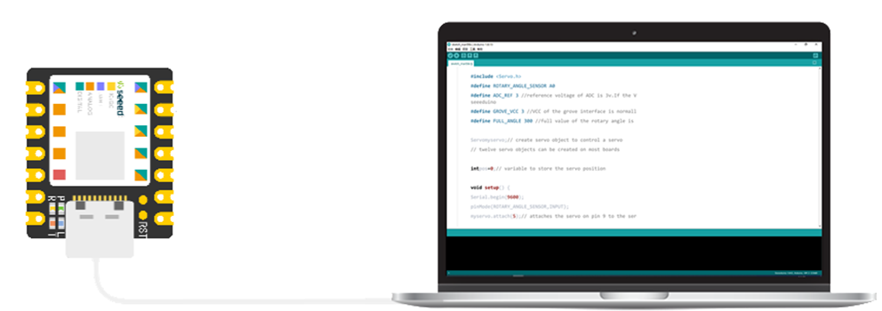
Connect XIAO to the computer with a data cable, as shown in the figure below: 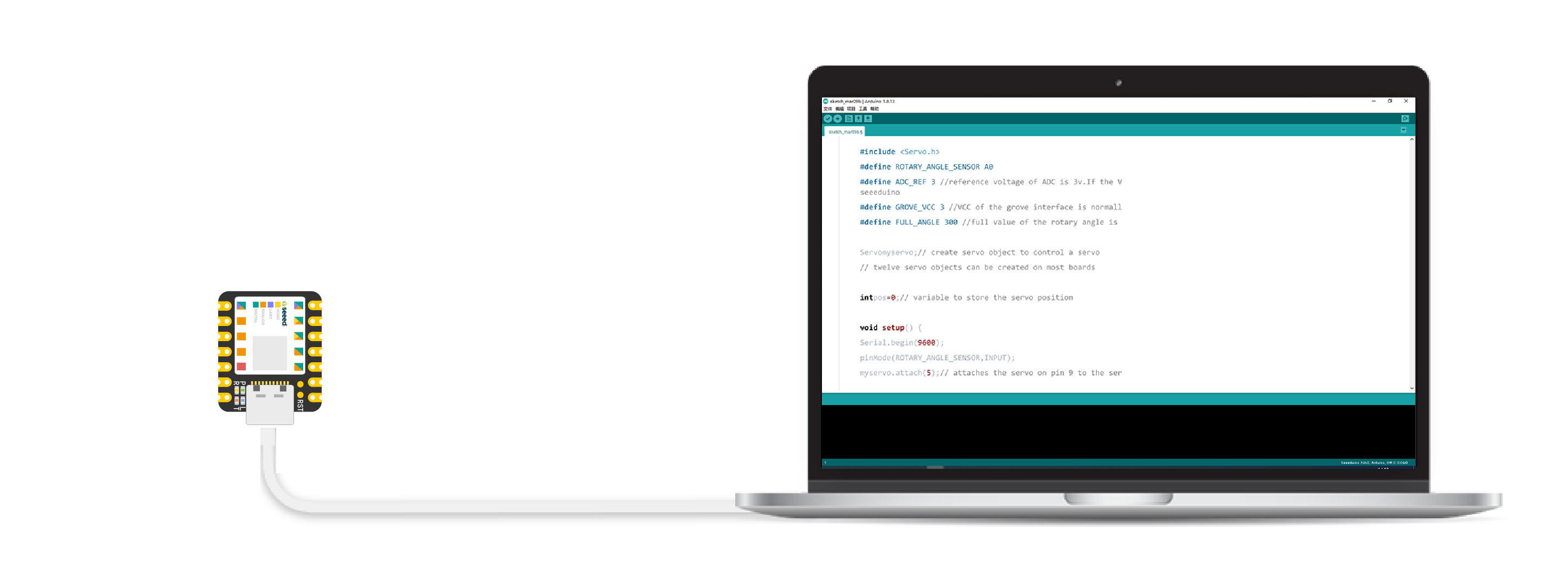
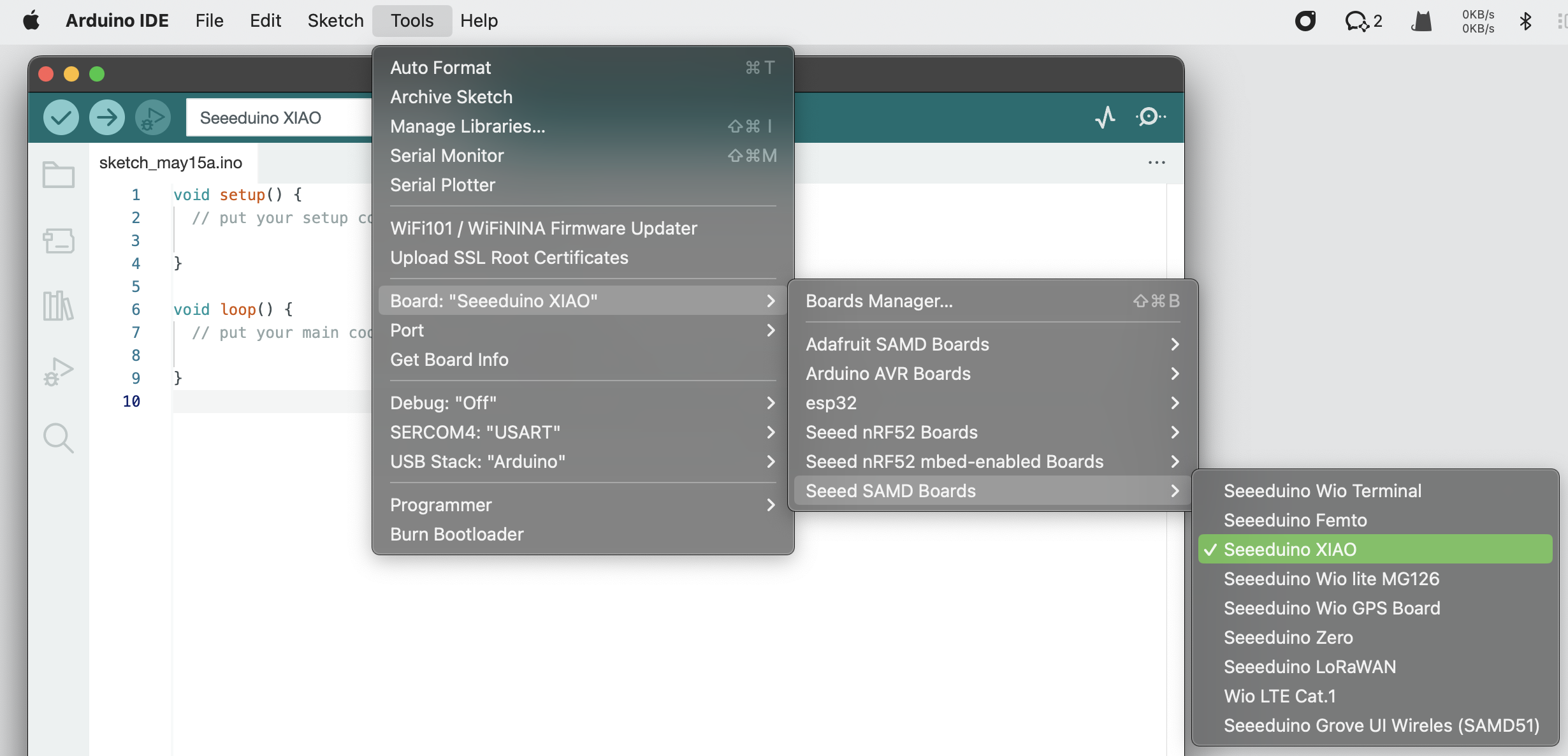
Next, click on “Tools→Board”, find “Seeeduino XIAO,” and select it, as shown in the figure below.
⚠️ Attention
If your development board is XIAO nRF52840, please select Seeed XIAO nrf52840.
If your development board is XIAO nRF52840 Sense, please select Seeed XIAO nrf52840 Sense.
If your development board is XIAO RP2040, please select Seeed XIAO RP2040.
If your development board is XIAO ESP32C3, please select XIAO_ESP32C3.
If your development board is XIAO ESP32S3, please select XIAO_ESP32S3.
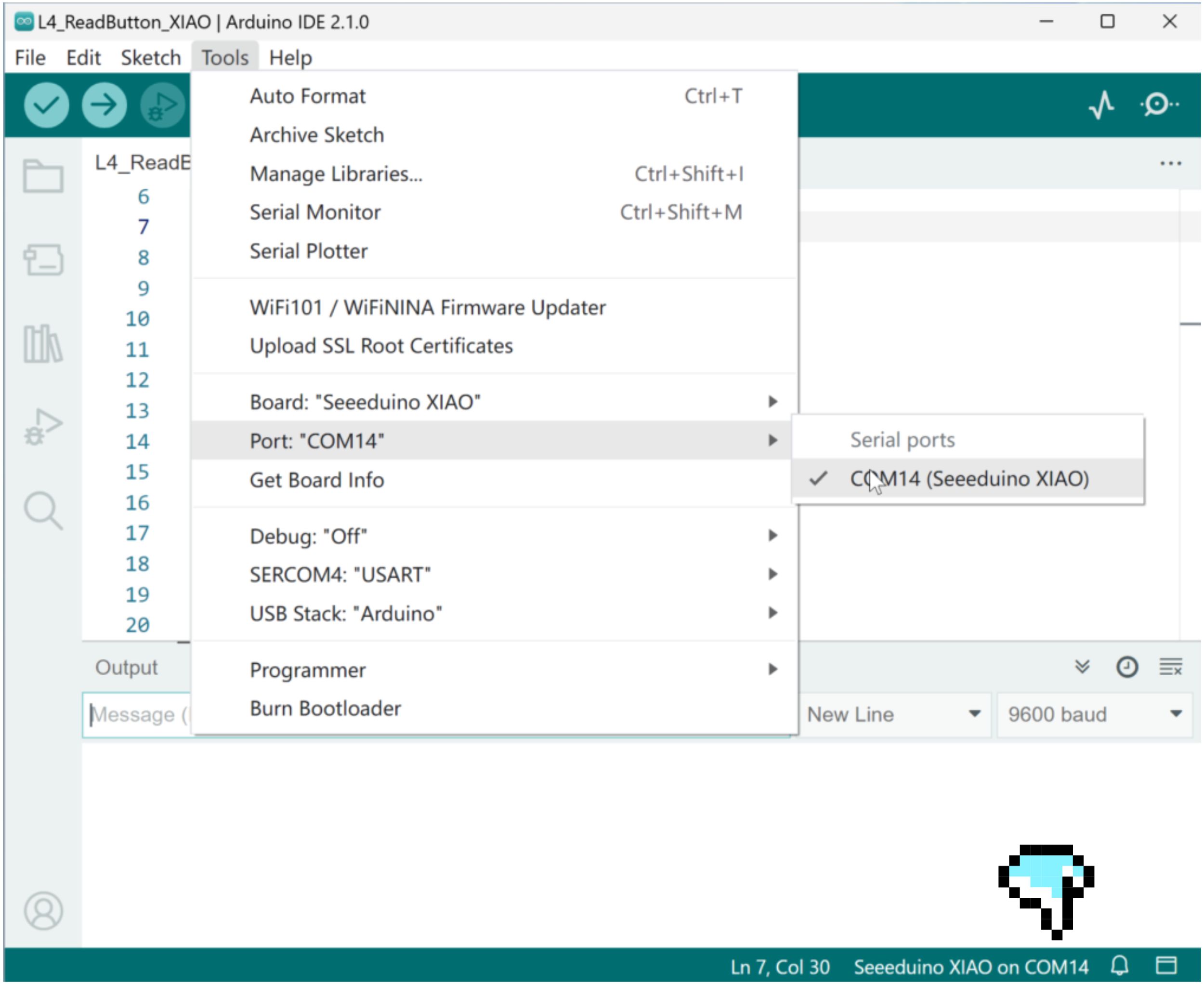
Check if the port connection is correct; if not, select it manually.
- The serial port on Windows systems is displayed as “COM+number,” as shown in the figure below.
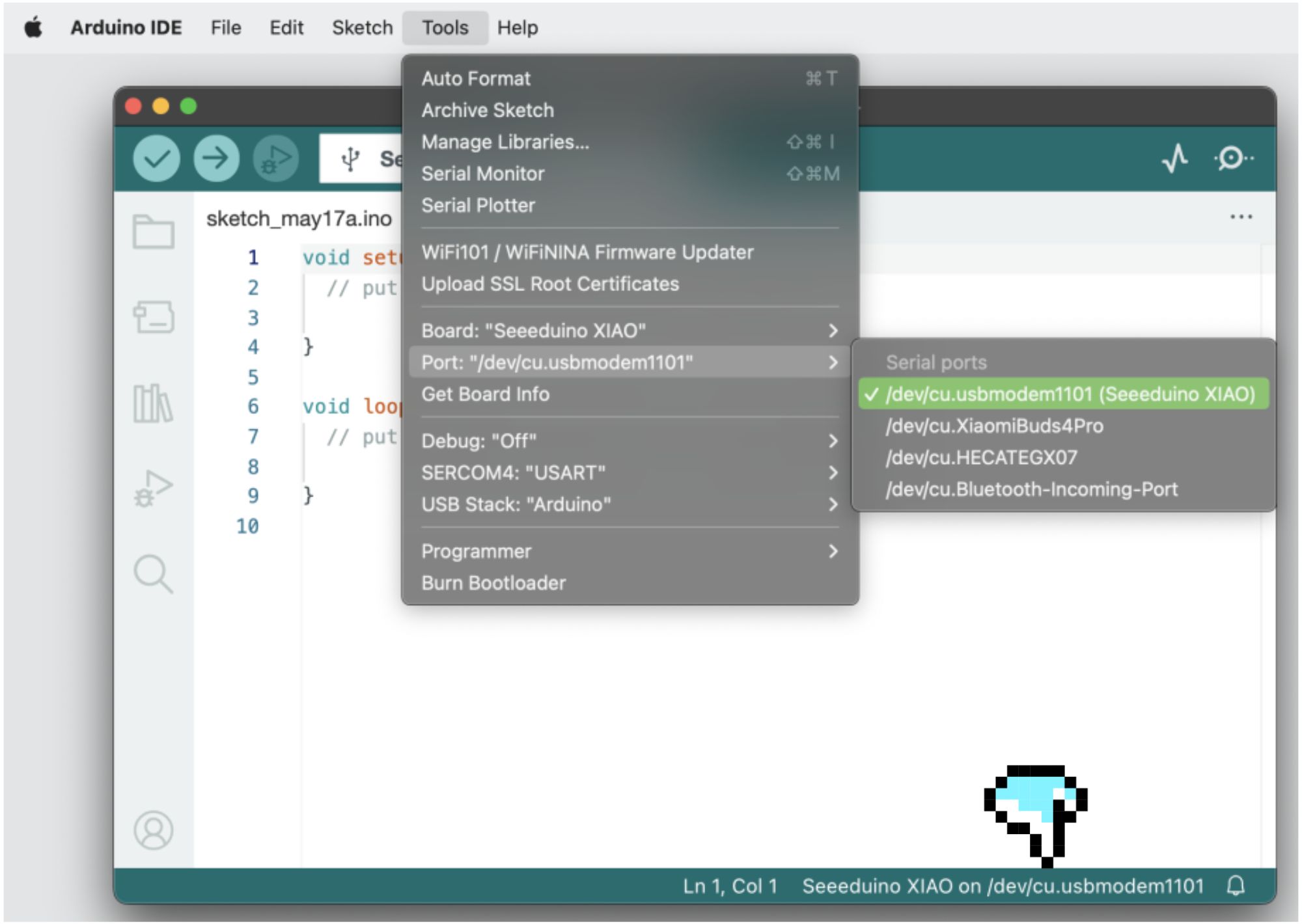
- The serial port name on Mac or Linux systems is generally /dev/tty.usbmodem+number or /dev/cu.usbmodem+number, as shown in the figure below.
Now, we can start programming XIAO through the software.
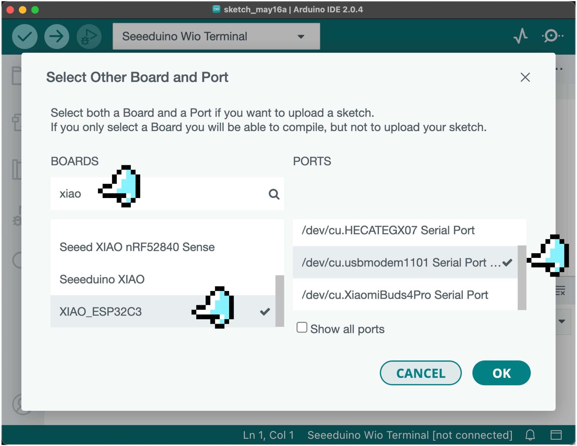
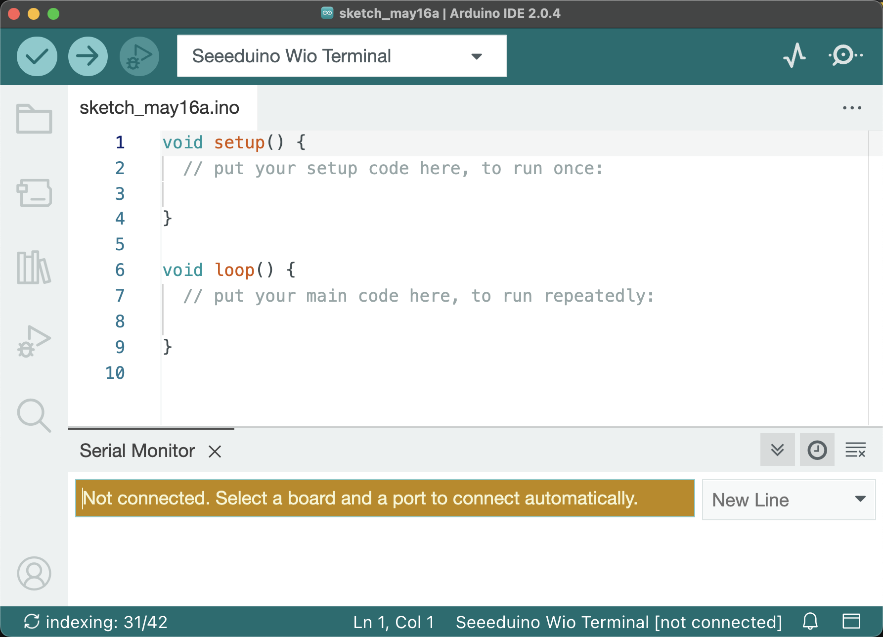
⚠️ XIAO ESP32C3 may not be adequately recognized in Arduino IDE 2, and you need to specify the development board and port manually.
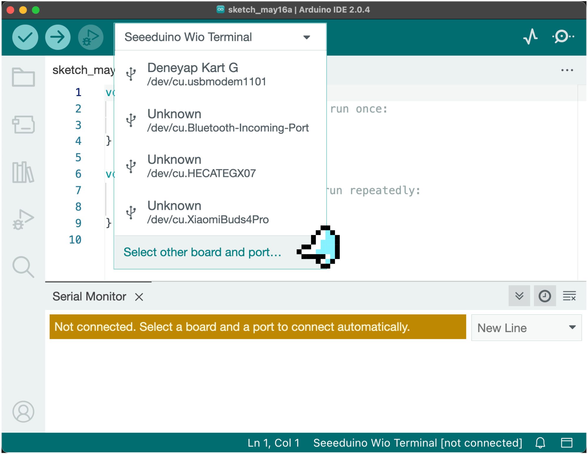
When ESP32C3 is plugged into a PC with Arduino IDE 2, it may not be able to match the correct development board automatically. As shown in the figure below, the display is not the XIAO ESP32 development board; you need to specify manually. Select ” Other Board & Port…” from the Port drop-down menu. Enter “xiao” in the search bar of the development board, select the XIAO_ESP32C3 development board from the filtered list below, and confirm after selecting the port on the right.
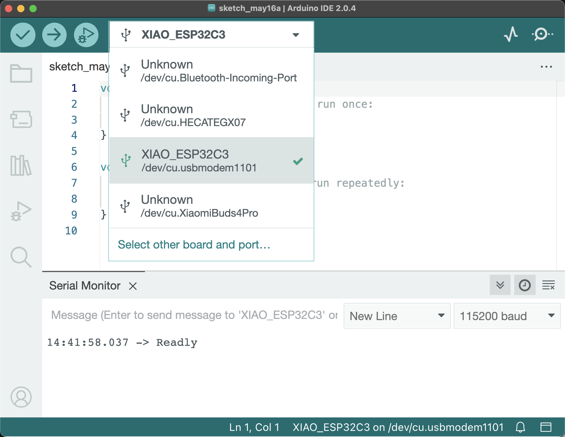
Now you can see that the development board and port are in the correct state.
⚠️ Reset Seeed Studio XIAO
Sometimes when the program upload fails, the Seeed Studio XIAO port may disappear, and we need to perform a reset operation. The reset method will be different for different models of XIAO.
Reset of Seeed Studio XIAO SAMD21
- Connect XIAO SAMD21 to your computer.
- Open “Blink” in the Arduino IDE sample program and click upload.
- While uploading, short circuit the RST pin in the figure once with tweezers or a short wire.
- The reset is completed when the orange LED flashes and lights up.
As shown in the figure below.  .
.
Reset of Seeed Studio XIAO PR2040
- Connect Seeed Studio XIAO RP2040 to your computer.
- Press the reset button marked with “R” once, the position is shown in the figure below.
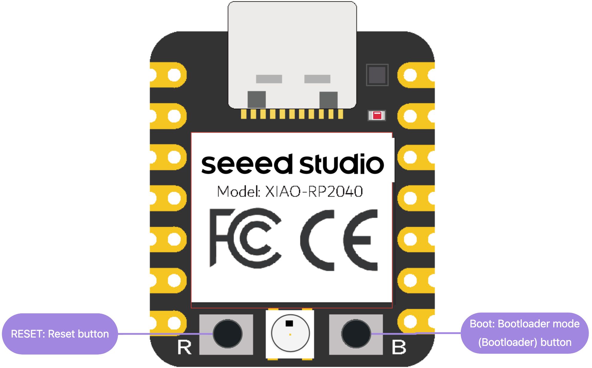
If this does not work, hold down the Boot button marked with “B”, connect the board to your computer while holding down the BOOT button, and then release it to enter the bootloader mode.
Reset of Seeed Studio XIAO nRF52840 and Sense version
- Connect Seeed Studio XIAO nRF52840 or Sense version to your computer.
- Press the reset button marked with “RST” once, the position is shown in the figure below.

If this does not work, you can quickly click it twice to enter the bootloader mode.
Reset of Seeed Studio XIAO ESP32C3
- Connect Seeed Studio XIAO ESP32C3 to your computer.
- Press the reset button marked with “R” once, the position is shown in the figure below.
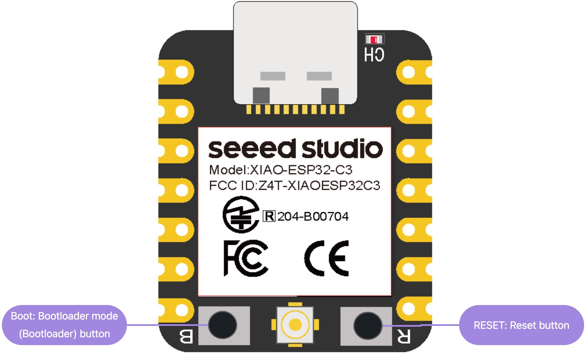
If this does not work, hold down the Boot button marked with “B”, connect the board to your computer while holding down the BOOT button, and then release it to enter the bootloader mode.
Reset of Seeed Studio XIAO ESP32S3
- Connect Seeed Studio XIAO ESP32S3 to your computer.
- Press the reset button marked with “R” once, the position is shown in the figure below.
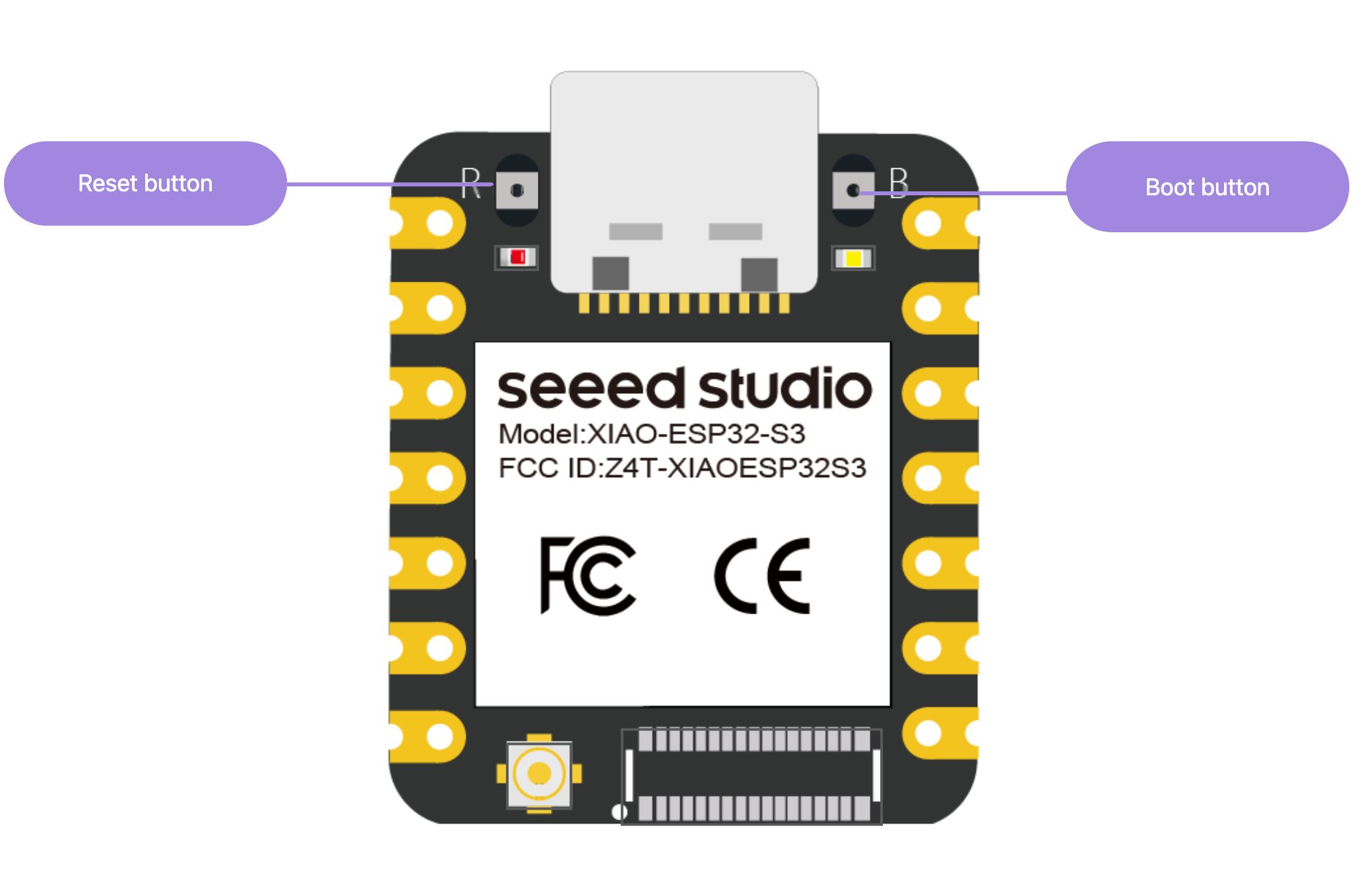
If this does not work, hold down the Boot button marked with “B”, connect the board to your computer while holding down the BOOT button, and then release it to enter the bootloader mode.
Structure of Arduino Programs
Now that we have the development board, how can we write programs into it to control its functions? That’s when the Arduino IDE text editor comes in handy. We’ve already introduced the interface functions of Arduino IDE in the introduction, it’s an important tool for writing and uploading programs. Arduino programs consist of two basic functions:
setup()
This function is called when the program begins. Use it to initialize variables, pin modes, start using libraries, etc. setup() runs only once each time the Arduino board is powered on or reset.
loop()
After the program in setup() is executed, the program in loop() begins to execute. The program in loop() runs repeatedly.
Knowledge window:
- The contents after “/* */” and “//” are comments to help you understand and manage code, the comments will not affect the normal operation of the program;
- When writing programs, we need to use “{}” to wrap a set of codes;
- After each line of code, use “;” as an end symbol to tell the Arduino editor that this line of code instruction is over.
Digital Signals and I/O Settings
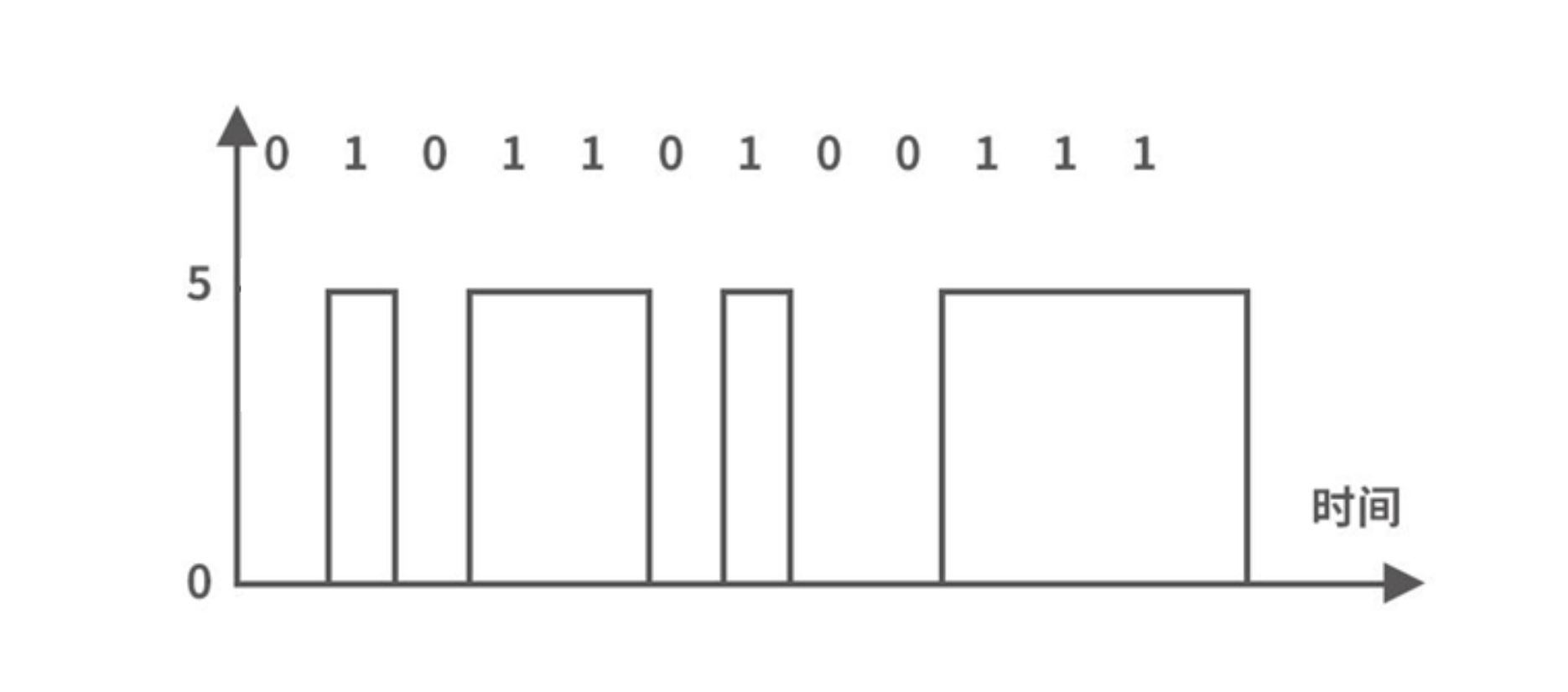
Simply put, digital signals are signals represented in binary form of 0 and 1. In Arduino, digital signals are represented by high and low levels, high level means digital signal 1, and low level means digital signal 0. Seeed Studio XIAO has 11 digital pins, we can set these pins to perform the function of inputting or outputting digital signals.
In Arduino, you can use functions to set the status and function of pins. Here are the basic steps to set pins through functions:
- First, determine the pin number of the pin you want to control.
- In the Arduino code, use the
pinMode()function to set the function of the pin, such as input or output. For example, to set the pin to output mode, you can use the following code:
int ledPin = 13; // The pin to be controlled
void setup() {
    pinMode(ledPin, OUTPUT); // Set the pin to output mode
}- Once you have set the pin to output mode, you can use the
digitalWrite()function to set the status of the pin, such as setting it to high or low level. For example, to set the pin to high level, you can use the following code:
digitalWrite(ledPin, HIGH); // Set the pin to high level- If you set the pin to input mode, you can use the
digitalRead()function to read the status of the pin, such as detecting whether it is high or low level. For example, to read the status of the pin and save it to a variable, you can use the following code:
int buttonPin = 2; // The pin to read the status from
int buttonState = 0; // The variable to save the status
void setup() {
    pinMode(buttonPin, INPUT); // Set the pin to input mode
}
void loop() {
    buttonState = digitalRead(buttonPin); // Read the status of the pin
}
By using functions like pinMode(), digitalWrite(), and digitalRead(), you can easily set and control the status and function of pins in Arduino.
1.1.3 Task 1: Run Blink to Make XIAO’s LED Flash
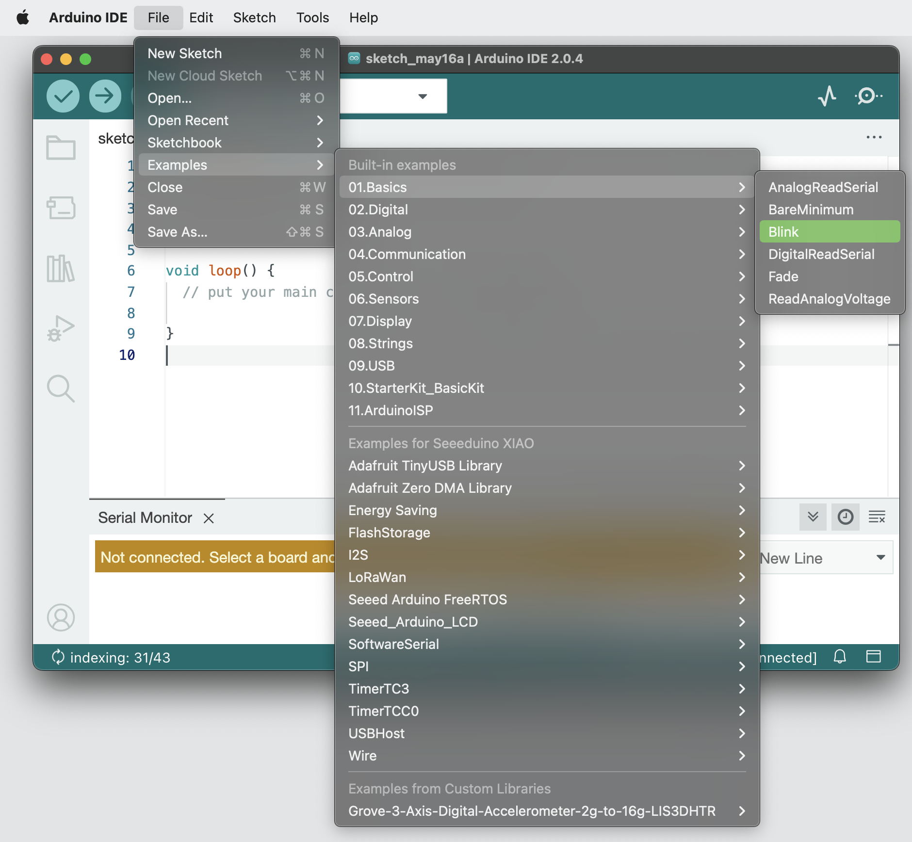
Just as “Hello World” is the first section in all programming languages, “Blink” is akin to “Hello World” in Arduino programming. It is the key to our journey in learning Arduino. Arduino provides many example codes to help us get started quickly, and Blink is one of them. We can select “File → Examples → 01.Basics → Blink” in the Arduino window to open the example program Blink.
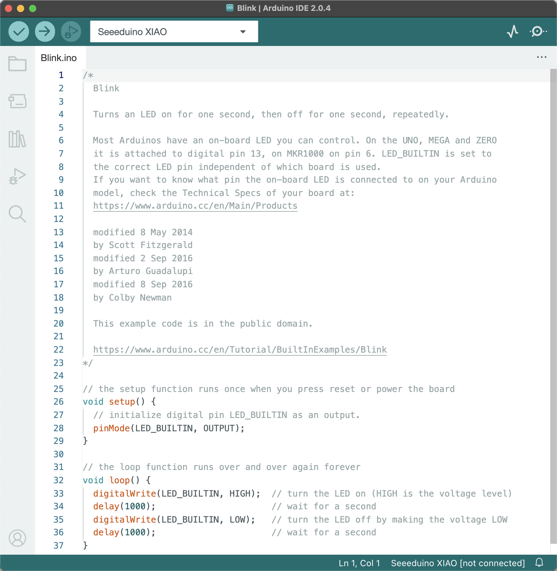
After opening the example program, you can see the following code, which implements the effect of LED flashing. You can see that the code has orange and green color prompts, which proves that your input is correct. Pay attention to the difference between uppercase and lowercase.
/*
  Blink

  Turns an LED on for one second, then off for one second, repeatedly.

  Most Arduinos have an on-board LED you can control. On the UNO, MEGA and ZERO
  it is attached to digital pin 13, on MKR1000 on pin 6. LED_BUILTIN is set to
  the correct LED pin independent of which board is used.
  If you want to know what pin the on-board LED is connected to on your Arduino
  model, check the Technical Specs of your board at:
  https://www.arduino.cc/en/Main/Products

  modified 8 May 2014
  by Scott Fitzgerald
  modified 2 Sep 2016
  by Arturo Guadalupi
  modified 8 Sep 2016
  by Colby Newman

  This example code is in the public domain.

  https://www.arduino.cc/en/Tutorial/BuiltInExamples/Blink
*/

// the setup function runs once when you press reset or power the board
void setup() {
  // initialize digital pin LED_BUILTIN as an output.
  pinMode(LED_BUILTIN, OUTPUT);
}

// the loop function runs over and over again forever
void loop() {
  digitalWrite(LED_BUILTIN, HIGH);  // turn the LED on (HIGH is the voltage level)
  delay(1000);                      // wait for a second
  digitalWrite(LED_BUILTIN, LOW);   // turn the LED off by making the voltage LOW
  delay(1000);                      // wait for a second
}
Code Analysis
pinMode(LED_BUILTIN, OUTPUT);
The first thing the code does is to initialize LED_BUILTIN as an output pin in the setup() function. Most Arduino series boards default the onboard LED to digital pin 13. The constant LED_BUILTIN connects the onboard LED to pin 13.
digitalWrite(LED_BUILTIN, HIGH);
In the loop() function, we set the LED_BUILTIN pin to the “on” state, outputting 5V or 3.3V voltage to this pin, which can be represented by HIGH. However, note that all I/O pins on XIAO are 3.3V. Do not input a voltage exceeding 3.3V, or it may damage the CPU.
digitalWrite(LED_BUILTIN, LOW);
What comes on must turn off. This statement sets the LED_BUILTIN pin to the “off” state, outputting 0V voltage to this pin, which can be represented by LOW.
delay(1000);
This is a delay statement. It means that the LED can maintain the “on” or “off” state for 1 second, because the parameter in the function is in milliseconds, so 1000 milliseconds is 1 second. After controlling the “on” and “off” statements of the LED, a delay must be added, and the waiting time should be the same to ensure that the LED flashes evenly.
Upload the Program
Next, we will learn how to upload the program. Use the data cable in the kit to connect XIAO to the computer, as shown in the figure.
Choose the serial port of the development board from the “Tools” bar. For Windows users, it is generally COM3 or a larger number. Select it as shown in the figure below.
If several ports are displayed for selection, unplug the data cable, reopen the “Tools” bar, and the port that disappears is the XIAO port. Reconnect the circuit board and then select this serial port. After selecting the board and the serial port, you can see the controller model and corresponding serial port that have been set up in the lower right corner of the IDE interface.
In Mac or Linux systems, the serial port name is generally /dev/tty.usbmodem+number or /dev/cu.usbmodem+number, as shown in the figure below.
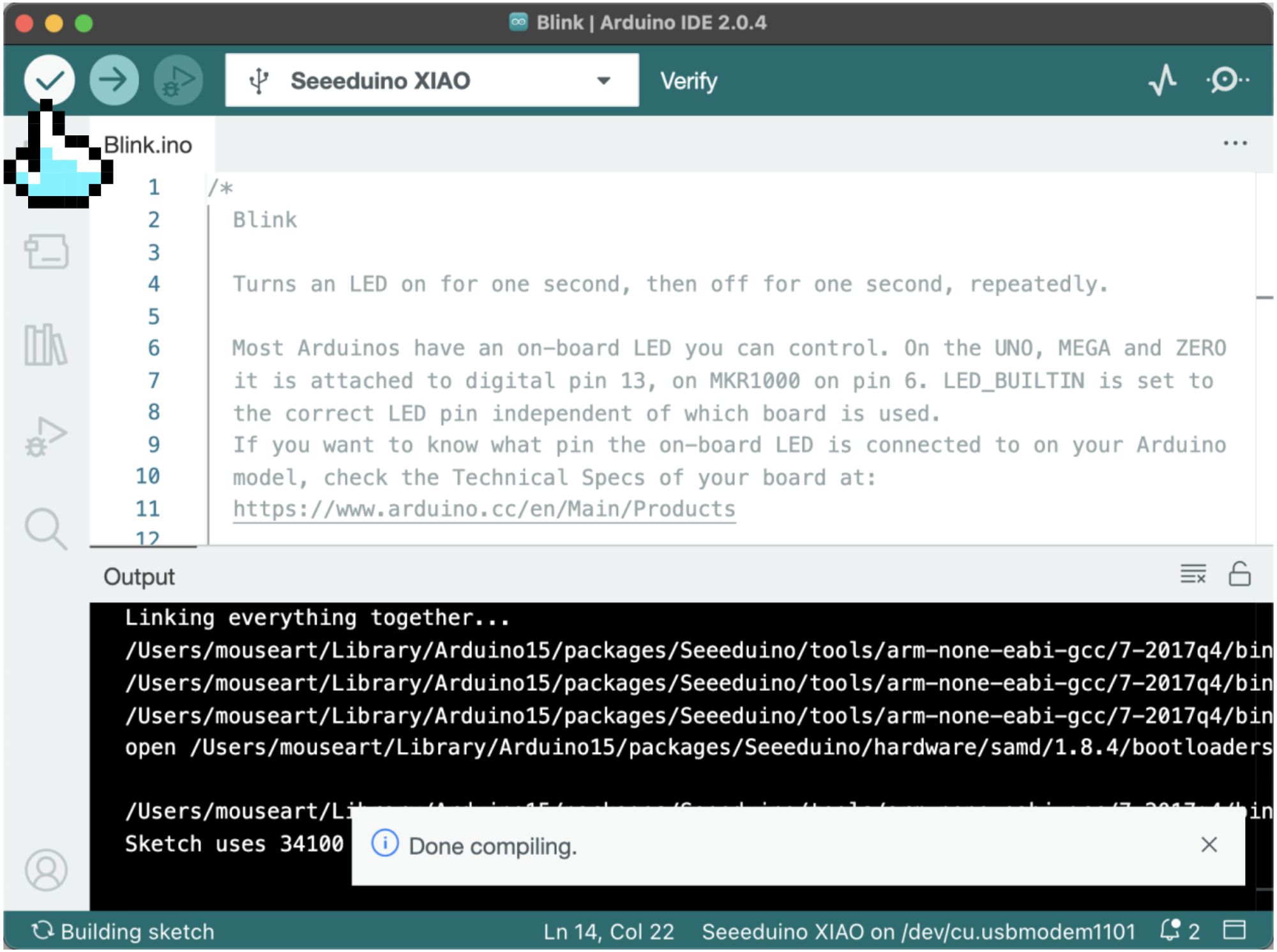
Next, we can upload the program. Before uploading, we can click the ![]() (verify button) to verify whether the program is correct. If “Compilation Completed” is displayed, the program is correct.
(verify button) to verify whether the program is correct. If “Compilation Completed” is displayed, the program is correct.
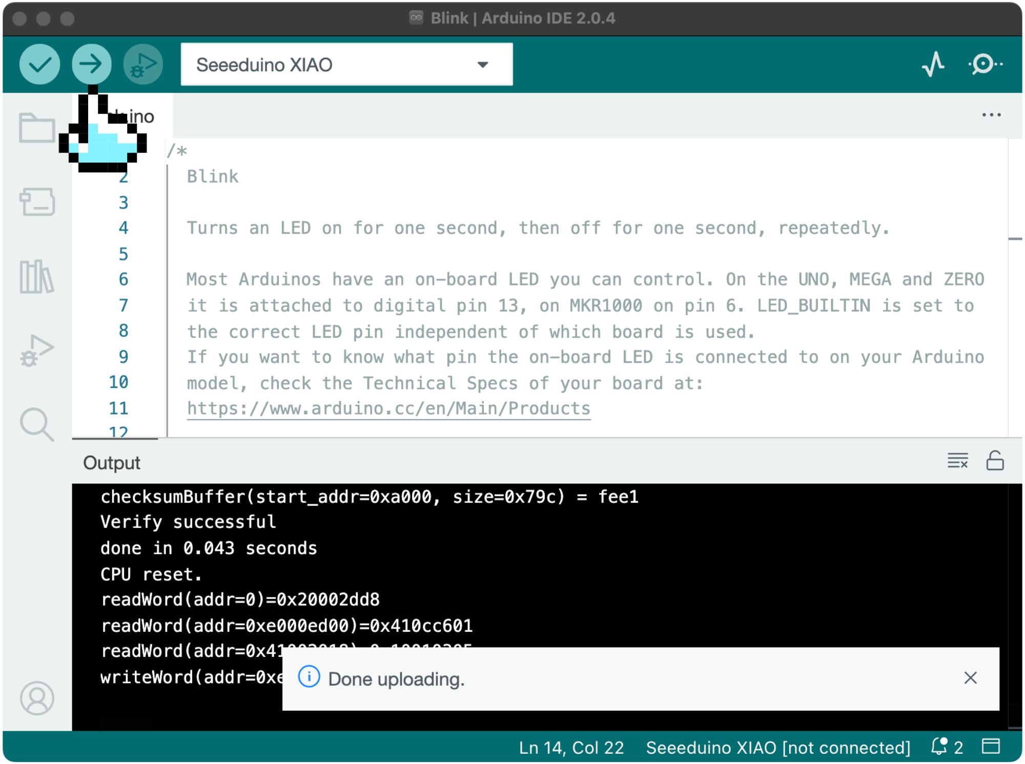
Click the ![]() (upload button), the debug window will display “Compiling Project→Upload”. When “Upload Completed” is displayed, you can see the effect of the program running on XIAO, as shown in the upload successful prompt window displayed on a Mac computer.
(upload button), the debug window will display “Compiling Project→Upload”. When “Upload Completed” is displayed, you can see the effect of the program running on XIAO, as shown in the upload successful prompt window displayed on a Mac computer.
⚠️ Note
When you start writing code, you will often forget the rules of uppercase and lowercase, punctuation, and make mistakes. Therefore, try to write code by yourself instead of copying and pasting. After the example program is successfully uploaded, try to create a new Sketch and start manually inputting the code.
1.1.4 Task 2: Complete the Blink example by connecting an external LED to Seeed XIAO ESP32C3 without LED
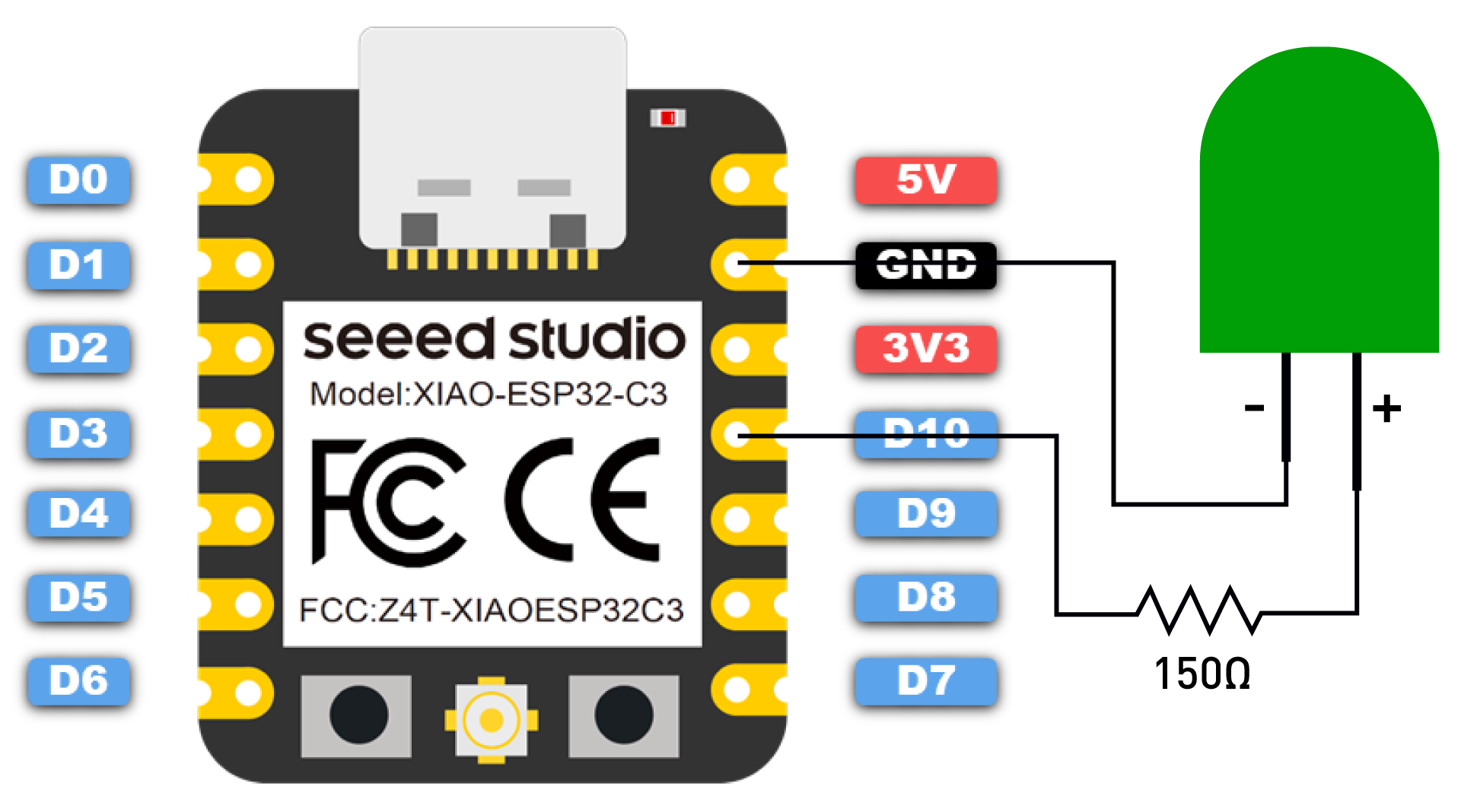
If the XIAO you have on hand is Seeed XIAO ESP32C3, since it does not have an onboard LED available for users, in order to run the Blink program, you need to first connect an LED to the D10 pin of the board, as shown below:
⚠️ Note
You must connect a resistor (about 150Ω) in series with the LED to limit the current flowing through the LED to prevent the strong current from burning the LED.
Then copy the following program to the Arduino IDE:
// Define the LED pin according to the pin diagram
int led = D10;

void setup() {
    // Initialize the digital pin 'led' as output
    pinMode(led, OUTPUT);
}

void loop() {
    digitalWrite(led, HIGH);   // Turn the LED on
    delay(1000);               // Wait for a second
    digitalWrite(led, LOW);    // Turn the LED off
    delay(1000);               // Wait for a second
}
Get this program from Github
https://github.com/mouseart/XIAO-Mastering-Arduino-and-TinyML/blob/main/code/L1_Blinks_XIAO_ESP32C3/L1_Blinks_XIAO_ESP32C3.ino
Code Analysis
int led = D10;
Seeed XIAO ESP32C3 does not have an onboard LED, so we did not preset an LED corresponding pin in the Arduino core. Just now, we connected the LED to the D10 pin, so we need to declare it in the program.
pinMode(led, OUTPUT);
We defined led as D10, and this step is to initialize led(D10) as an output pin.
1.1.5 Extended Exercise
Rewrite the Blink program: In the example program, the LED is on and off for 1 second each time, so it seems to blink evenly. Try adjusting the waiting time to give the LED different blinking effects.
Hint:
void setup() {
    pinMode(LED_BUILTIN, OUTPUT);
}
void loop() {
    digitalWrite(LED_BUILTIN, HIGH);
    delay(1000);
    digitalWrite(LED_BUILTIN, LOW);
    delay(500);
}
Get this program from Github
https://github.com/mouseart/XIAO-Mastering-Arduino-and-TinyML/blob/main/code/L1_ll_Blinks_1_en/L1_ll_Blinks_1_en.ino
For XIAO ESP32C3, we also need to modify the pin definition part of the program:
int led = D10;
void setup() {
    pinMode(led, OUTPUT);
}
void loop() {
    digitalWrite(led, HIGH);
    delay(1000);
    digitalWrite(led, LOW);
    delay(500);
}
Get this program from Github
https://github.com/mouseart/XIAO-Mastering-Arduino-and-TinyML/blob/main/code/L1_ll_blinks_2_en/L1_ll_blinks_2_en.ino