3.1 Smart Remote Control Door
In everyday life, privacy and security are matters of great concern to everyone. In recent years, the doors of residential areas have become increasingly smart, only accessible through electronic keys or passwords, preventing outsiders from gaining entry. In public areas or parking lot entrances, having a smart remote control to operate doors could facilitate the work of security personnel. A simple smart remote control door can be implemented using an infrared transmitter and an infrared receiver, which sends and receives infrared signals to open and close the door. In this section, we will build such a smart remote control door.
3.1.1 Background Knowledge
3.1.1.1 Infrared Receivers and Transmitters
An infrared receiver is used to receive infrared signals, and is also used for remote control detection. The infrared receiver has an infrared detector for picking up the infrared light emitted by the infrared transmitter. The Grove - IR Infrared Receiver Module has a range of 10 meters; signals cannot be received beyond this effective range. Generally, the infrared receiver and infrared transmitter work together.
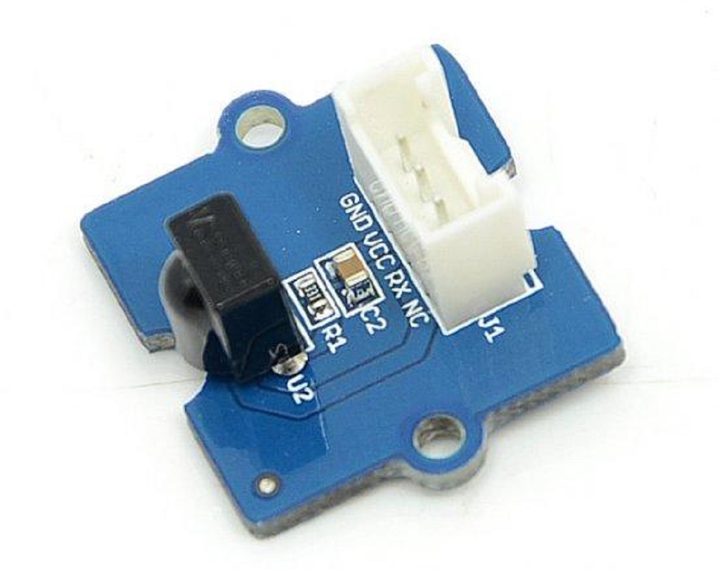
Grove - IR Infrared Receiver Module
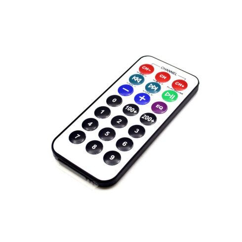
An infrared transmitter is a type of remote control device with a remote control function. It emits light through an infrared emission tube within a certain range, thereby achieving control signal functions. The remote controls we use to control TVs, air conditioners, and car doors in daily life are infrared transmitters. Common infrared transmitters include modular ones like the Grove - Infrared Emitter Module, as well as regular remote controls, each with corresponding usage scenarios and methods. For our smart remote control door, we will be using an infrared remote control.
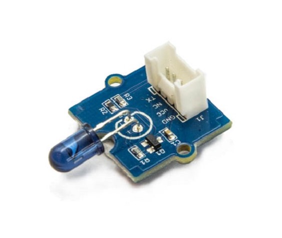
Grove - Infrared Emitter Infrared Transmitter Module
Grove - Infrared Emitter Infrared Transmitter Module
To explain simply, the principle of infrared transmission and reception is that the infrared transmitter inputs the signal, amplifies it, and sends it through the infrared transmission tube. The infrared receiver then receives this infrared signal, amplifies it and converts it back to an electrical signal, thereby realizing infrared control.
3.1.2 Task 1: Reading Remote Control Key Codes
Adding the Arduino-IRremote Library File
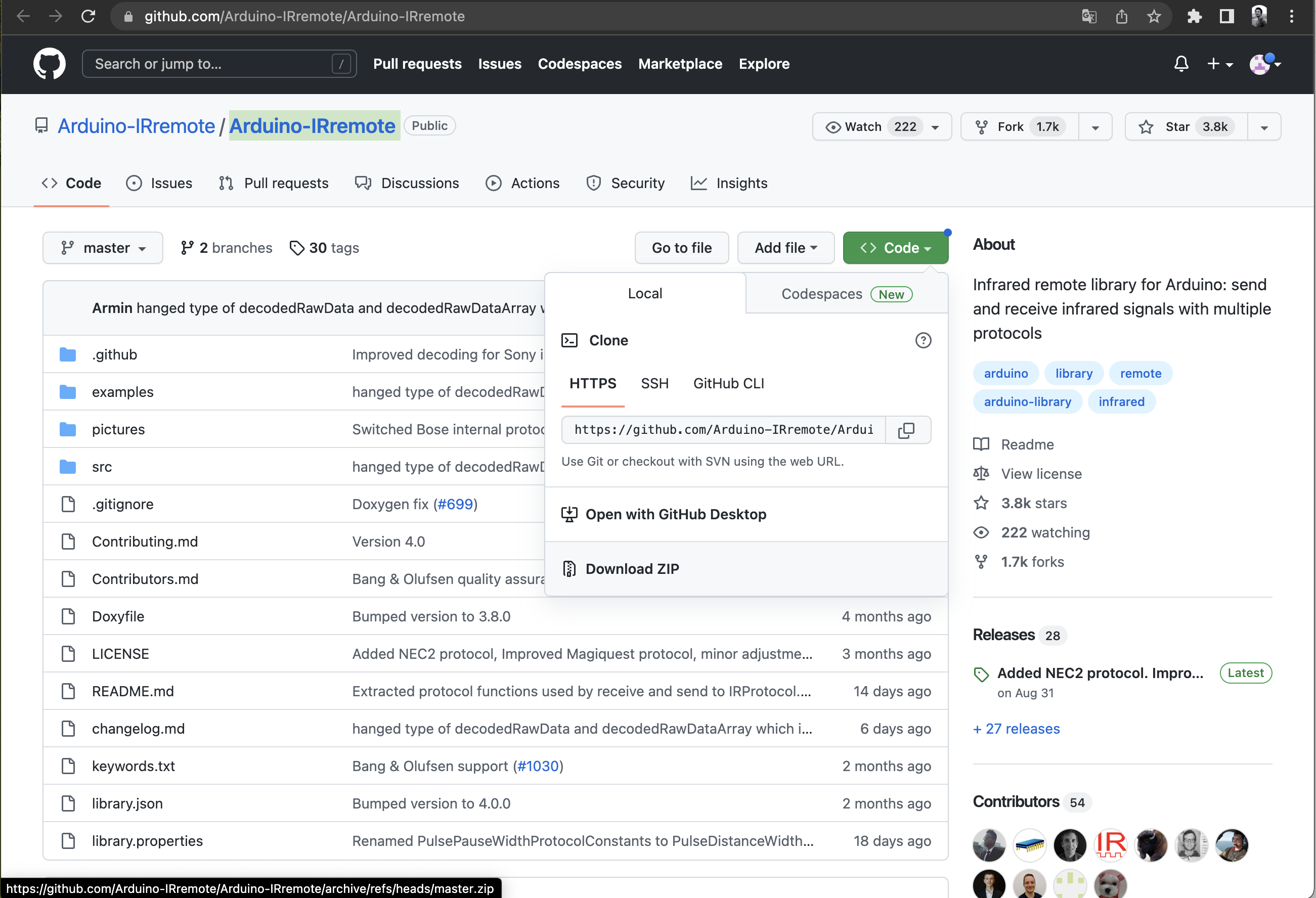
Before we begin programming the Grove - IR Infrared Receiver with the Arduino IDE, we need to add the necessary library files. Enter the library file address 🔗 https://github.com/Arduino-IRremote/Arduino-IRremote in your browser address bar, go to the GitHub page, and click Code→Download ZIP to download the resource package Arduino-IRremote-master.zip to your local machine, as shown in the image below:
Add the resource package Arduino-IRremote-master.zip you just downloaded through Sketch→Include Library→Add .ZIP Library in the Arduino IDE menu bar until you see a message indicating successful library loading.
Open the Example File
If you want to control other devices through the infrared remote control, such as pressing the left key on the mini infrared remote control to rotate the servo to the left, or pressing the right key to rotate the servo to the right, you first need to know what kind of code each key on the remote control will emit. This way, you can set it through the program. But how do you read the codes of different keys on the remote control? You can use the IRremote library and open the IRrecvDemo example via the following path: **File→Examples→IRremote→ReceiveDemo**. This example program can read the key codes of the remote control, but some parameters need to be modified:
**int RECV_PIN = 7**, change the number according to the hardware connection pin. We have connected the infrared receiver to pin 7. Next, we select useful code. We only need to define the header file and the part that reads the remote control key codes. After reducing, the program is as follows:
#include <Arduino.h>
#include <IRremote.h>

const byte IR_RECEIVE_PIN=7; // The infrared receiver is connected to pin 7. If you are using XIAO RP2040/XIAO ESP32, please change 7 to A0

void setup() {
    Serial.begin(115200);
    Serial.println(F("Enabling IRin"));
    IrReceiver.begin(IR_RECEIVE_PIN,ENABLE_LED_FEEDBACK); // Start infrared decoding
    Serial.print(F("Ready to receive IR signals at pin "));
    Serial.println(IR_RECEIVE_PIN);
    delay(1000);
}

void loop() {
    if (IrReceiver.decode()) // Decode successfully, receive a set of infrared signals
   {
      Serial.println(IrReceiver.decodedIRData.command, HEX); // Output infrared decoding result (hexadecimal)
      Serial.println(IrReceiver.decodedIRData.command); // Output infrared decoding result (octal)
      IrReceiver.resume(); // Receive the next set of values
   }
}
Get this program from Github
https://github.com/mouseart/XIAO-Mastering-Arduino-and-TinyML/tree/main/code/L11_IRrecvDemo_en
The infrared receiver module is connected to the port 7, as shown in the following figure:
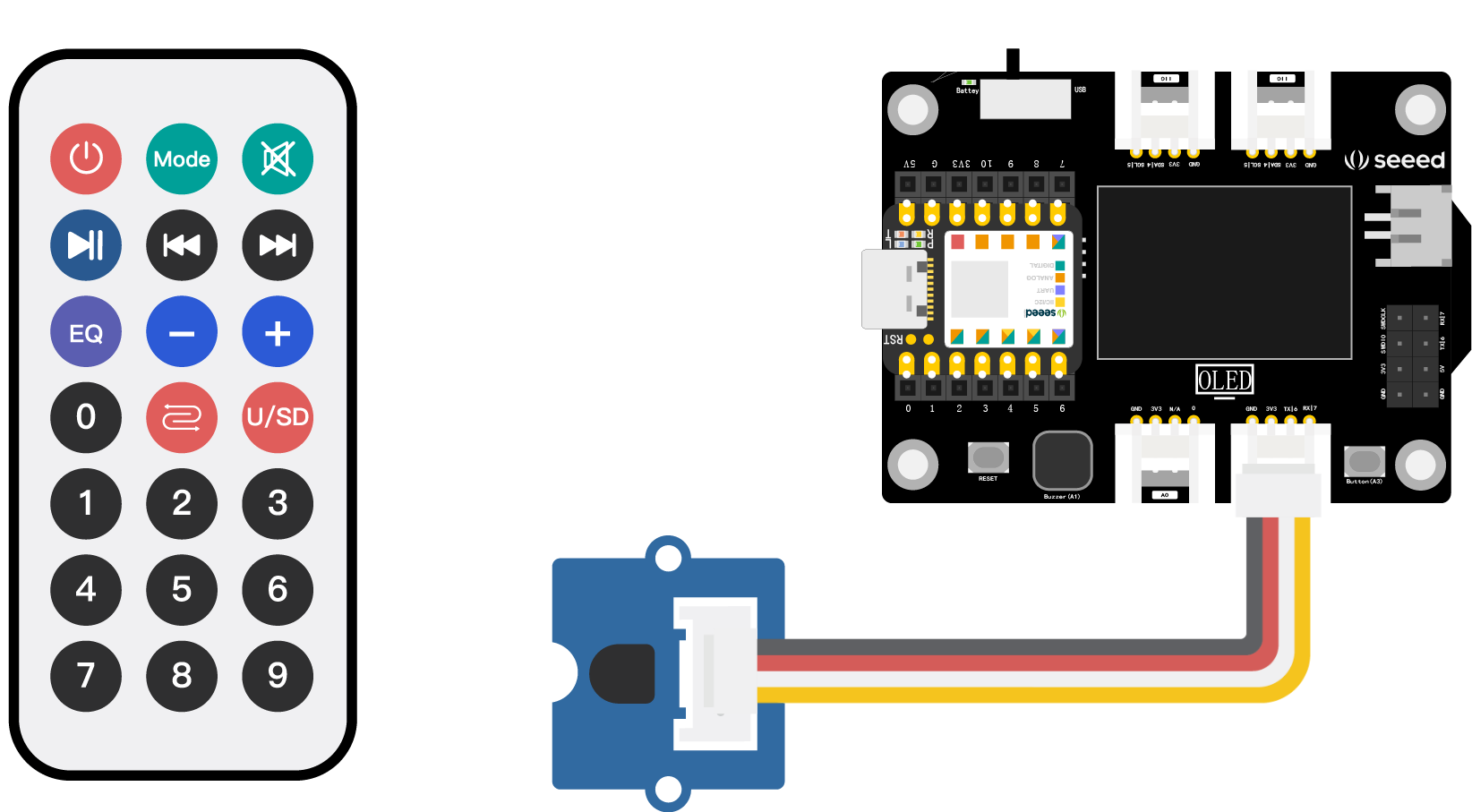
⚠️ Note:
If you are using XIAO RP2040/XIAO ESP32, please change7toA0.
After the code is uploaded, open the serial monitor, aim the remote control at the black component of the infrared receiver at a close distance, press any key, and observe the characters output by the serial monitor. The hexadecimal code appears in the first line, and the octal code appears in the second line. The two lines form one group, representing one key. Please note that if you press the key for too long, “FFFFFFFF” will appear, and this line of code and the numeric code below are invalid.
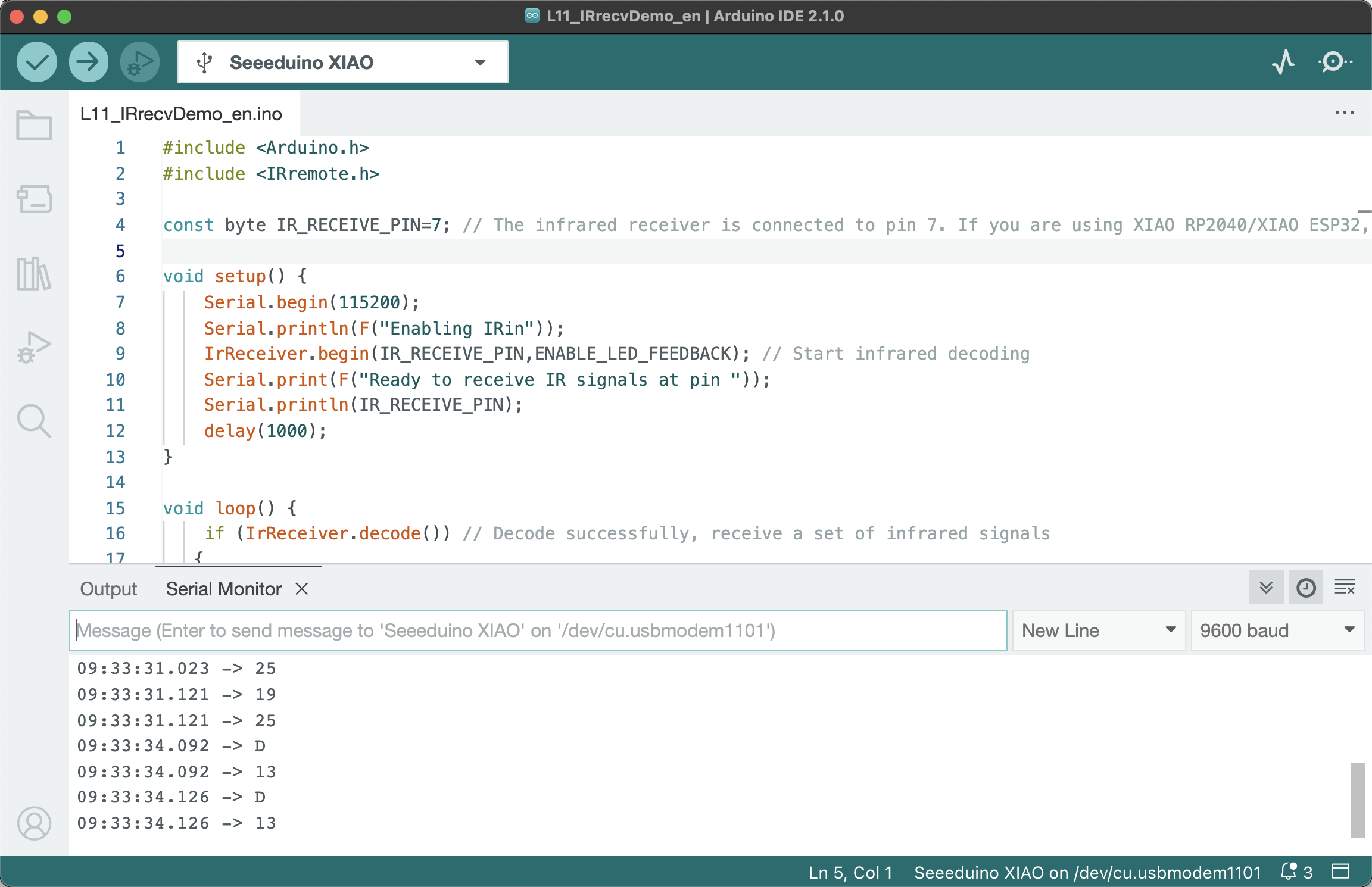
⚠️ Note: Different remote controls may give different values.
3.1.3 Project Creation: Smart Remote Door
Project Description
How can we recreate a smart remote control door? With a remote control and an infrared receiver, the next step is to control the opening and closing of the door. Recall how the remote control doors in our life work? When the remote control is pressed, the door slowly opens. When it opens to a certain angle, it slowly closes. We can use a servo to control the rotation of the door. When closing the door, the servo rotates from 90° to 0°. When opening the door, the servo rotates from 0° to 90°. By transmitting the signals to open and close the door with a remote control, we can implement the function of a smart remote control door.
Program Writing
To control the rotation of the servo with an infrared remote control, you need to follow these steps:
- Declare the
IRremotelibrary andServelibrary to be called, and define variables. - Initialize the library files, initialize the servo.
- Read the infrared decoding result and control the rotation of the servo according to the instructions to the left and right.
Task 2: Control the Rotation of the Servo with an Infrared Remote Control
Step 1: Declare the IRremote library and Serve library to be called, and define variables.
#include <IRremote.h>
#include <Servo.h>

Servo myservo; // Create a servo object myservo to control the servo
int RECV_PIN = 7; // The infrared receiver is connected to pin 7. If you are using XIAO RP2040/XIAO ESP32, please change 7 to A0
IRrecv irrecv(RECV_PIN); // Define an IRrecv object to receive infrared signals
decode_results results; // Decoding results are placed in results

int pos = 90; // Define pos as 90°
Step 2: Initialize the library files, initialize the servo.
void setup()
{
    Serial.begin(9600);
    Serial.println("Enabling IRin");
    irrecv.enableIRIn();
    myservo.attach(5); // Connect the servo on pin 5 to myservo. If you are using XIAO RP2040/XIAO ESP32, please change 5 to D5
}
Step 3: Read the infrared decoding result and control the rotation of the servo according to the instructions to the left and right. If you have questions about the program, you can refer to the comment section.
⚠️ Note: In the example, the infrared signal value of the right key
16761405, and the infrared signal value of the left key16712445, need to be replaced by the values obtained from the “Read Remote Control Key Code” example using the remote control in your hand. Otherwise, there will be no response after pressing the key.
void loop() {
    if (irrecv.decode(&results)) {  // If decoding is successful, a set of infrared signals is received
        if (results.value == 16761405) {  // If the received signal is 16761405 (right key)
            for (pos; pos <= 89; pos += 1) { // Then the servo is incremented from 0° to 90° in sequence
                myservo.write(pos);              // Write the rotation angle value to the servo pin
                delay(40);
                // The following is to interrupt the above instruction and exit the loop
                if (irrecv.decode(&results)) {
                    irrecv.resume();
                    if (results.value == 16712445)
                        break;
                }
            }
        }

        if (results.value == 16712445) {    // If the received signal is 16712445 (left key)
            for (pos; pos >= 1; pos -= 1) { // Then the servo is decremented from 90° to 0° in sequence
                myservo.write(pos);              // Write the rotation angle value to the servo pin
                delay(40);
                // The following is to interrupt the above instruction and exit the loop
                if (irrecv.decode(&results)) {
                    irrecv.resume();
                    if (results.value == 16761405)
                        break;
                }
            }
        }
        // Display hexadecimal and octal codes in the serial port
        Serial.println(pos);
        Serial.println(results.value, HEX);
        Serial.println(results.value);
        irrecv.resume();

    }
    delay(100);
}
Complete program details:
#include <IRremote.h>
#include <Servo.h>

Servo myservo; // Create a servo object myservo to control the servo
int RECV_PIN = 7; // The infrared receiver is connected to pin 7. If you are using XIAO RP2040/XIAO ESP32, please change 7 to A0
IRrecv irrecv(RECV_PIN); // Define an IRrecv object to receive infrared signals
decode_results results; // Decoding results are placed in results

int pos = 90; // Define pos as 90°

void setup()
{
    Serial.begin(9600);
    Serial.println("Enabling IRin");
    irrecv.enableIRIn();
    myservo.attach(5); // Connect the servo on pin 5 to myservo. If you are using XIAO RP2040/XIAO ESP32, please change 5 to D5
}

// Note: Left 16712445 Right 16761405, please replace with the key values read from your own remote control
void loop() {
    if (irrecv.decode(&results)) {  // If decoding is successful, a set of infrared signals is received
        if (results.value == 16761405) {  // If the received signal is 16761405 (right key)
            for (pos; pos <= 89; pos += 1) { // Then the servo is incremented from 0° to 90° in sequence
                myservo.write(pos);              // Write the rotation angle value to the servo pin
                delay(40);
                // The following is to interrupt the above instruction and exit the loop
                if (irrecv.decode(&results)) {
                    irrecv.resume();
                    if (results.value == 16712445)
                        break;
                }
            }
        }

        if (results.value == 16712445) {    // If the received signal is 16712445 (left key)
            for (pos; pos >= 1; pos -= 1) { // Then the servo is decremented from 90° to 0° in sequence
                myservo.write(pos);              // Write the rotation angle value to the servo pin
                delay(40);
                // The following is to interrupt the above instruction and exit the loop
                if (irrecv.decode(&results)) {
                    irrecv.resume();
                    if (results.value == 16761405)
                        break;
                }
            }
        }
        // Display hexadecimal and octal codes in the serial port
        Serial.println(pos);
        Serial.println(results.value, HEX);
        Serial.println(results.value);
        irrecv.resume();

    }
    delay(100);
}
Get this program from Github
https://github.com/mouseart/XIAO-Mastering-Arduino-and-TinyML/tree/main/code/L11_IR_Servo_ino_XIAO_en
Step 4: Connect the hardware and upload the program. First, connect the infrared receiving module to the 7th interface of the XIAO expansion board, and connect the servo to the I2C interface, as shown in the figure below:
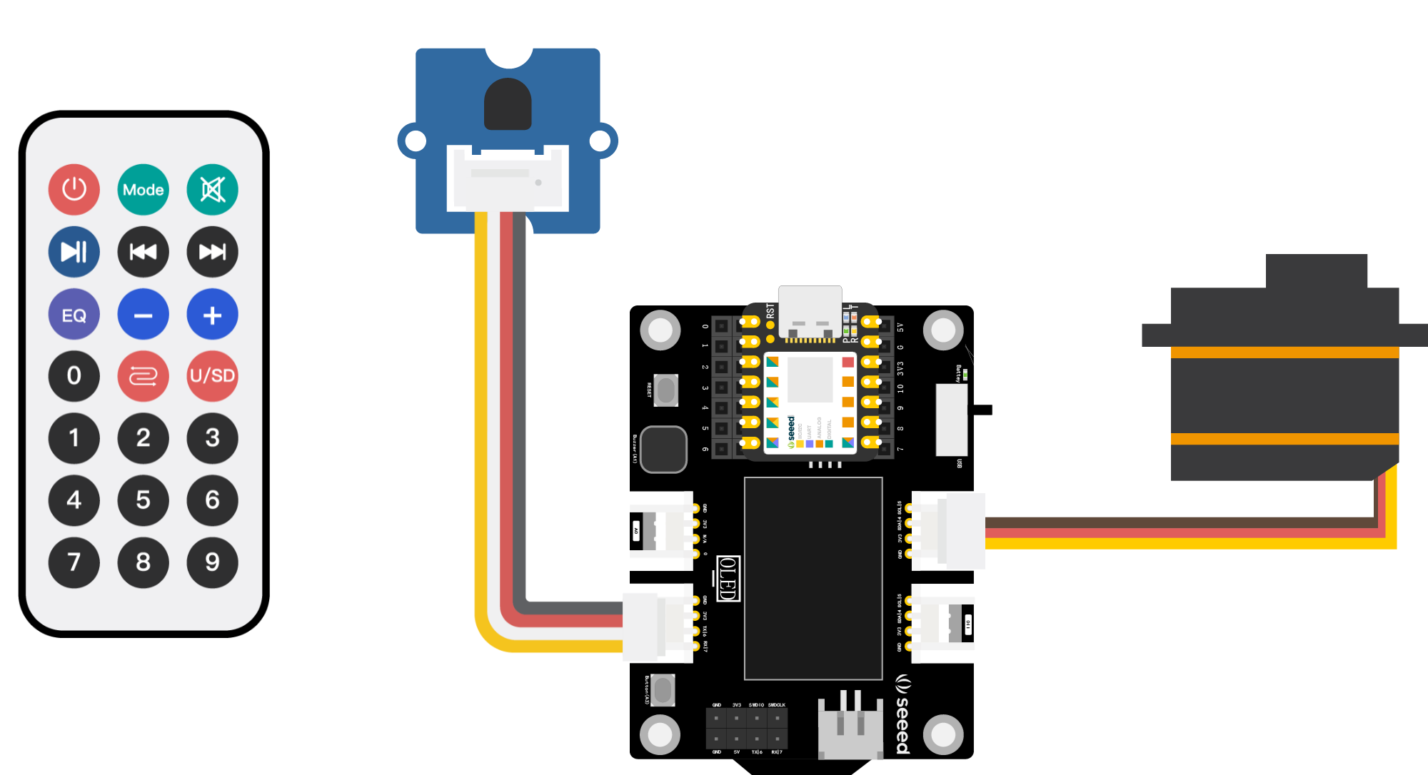
⚠️ Note:
If you are using XIAO RP2040, please connect the infrared receiving module to theA0interface.
Connect XIAO to the computer with a data cable, click the “Upload” button, upload the program to the hardware, and when the debug area shows “Upload Successful”, open the serial monitor, aim the remote control at the infrared receiver, press the “Left” key and the “Right” key, observe the rotation of the servo, and check the encoding information output by the serial monitor.
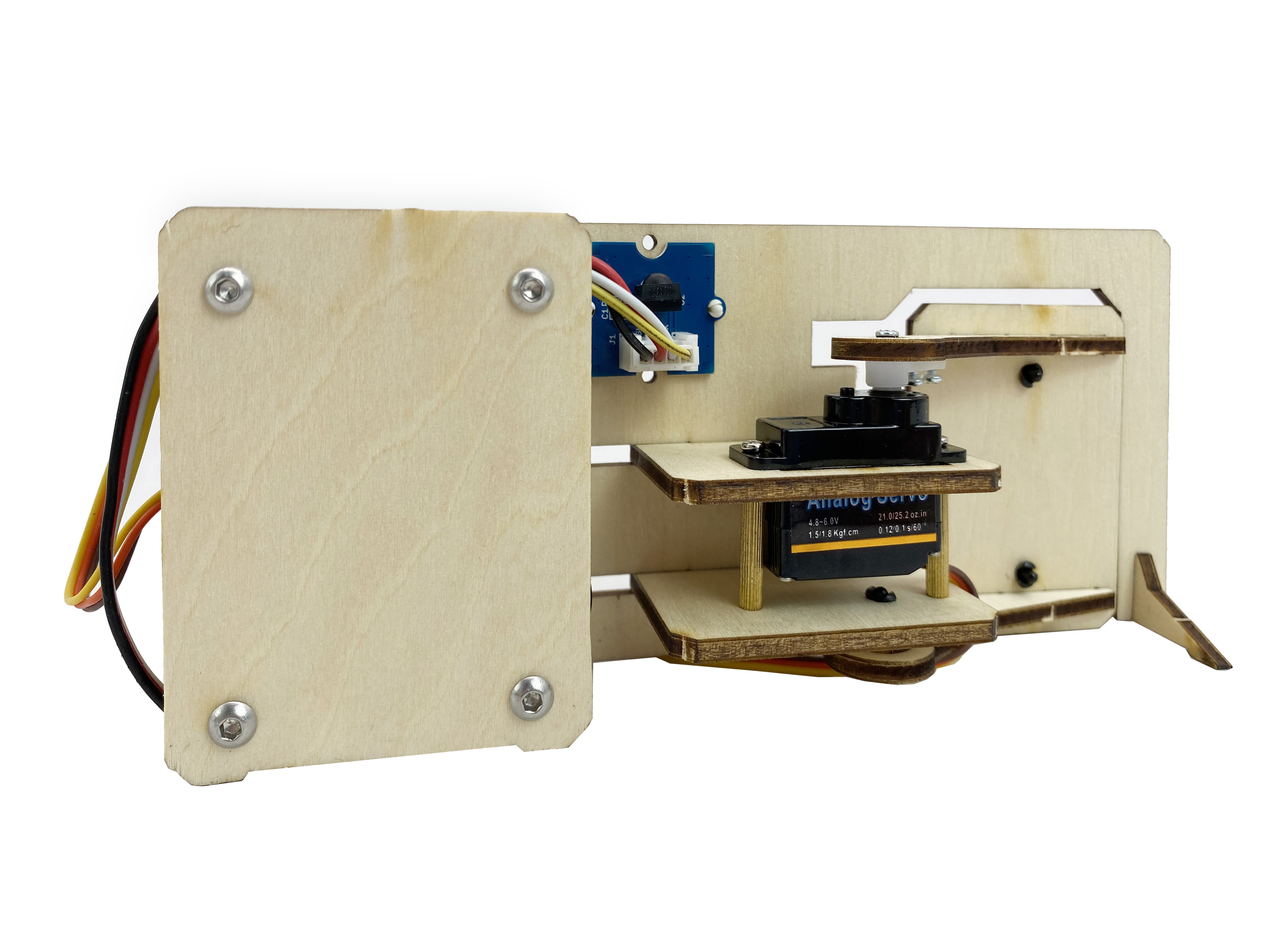
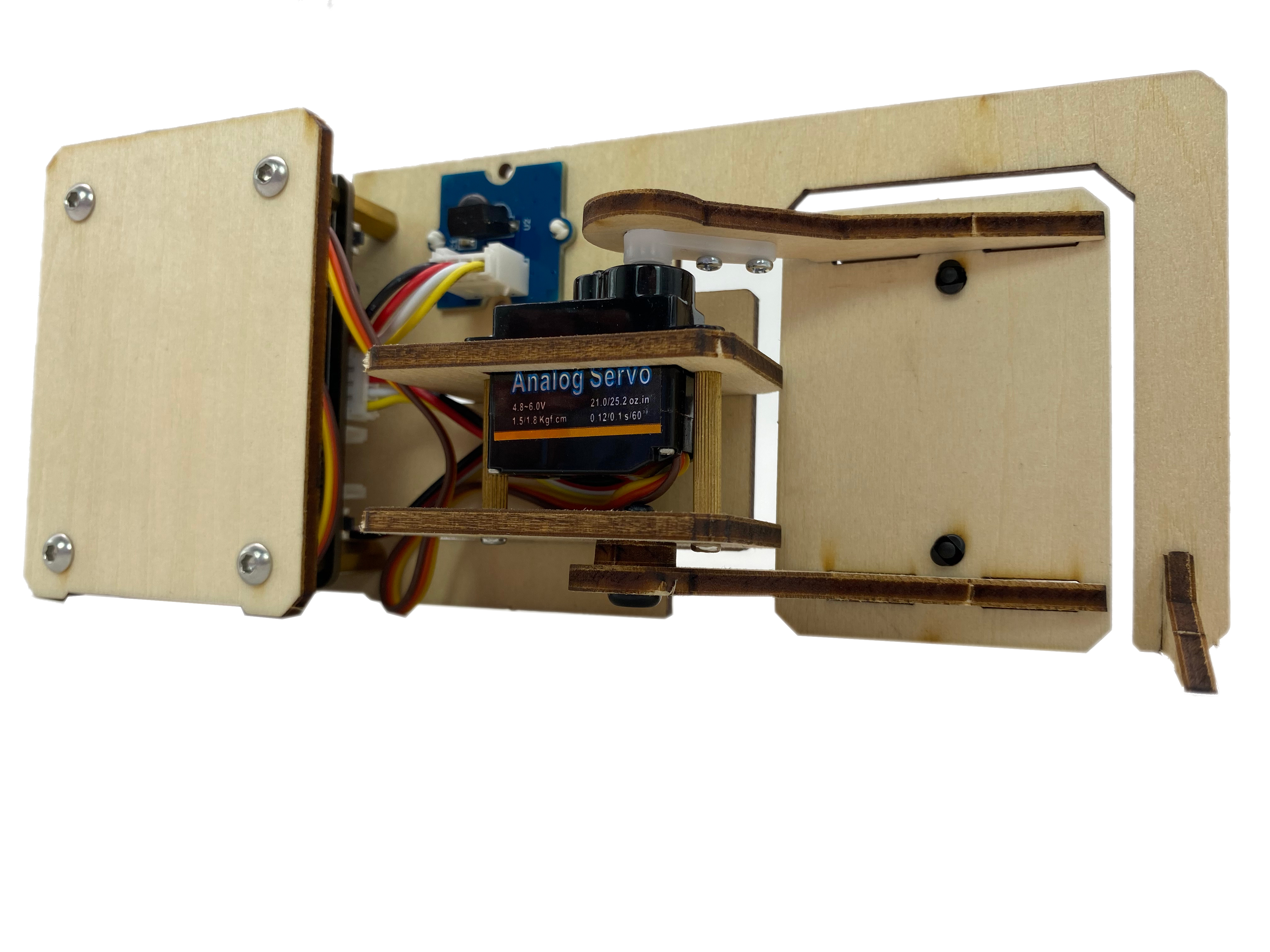
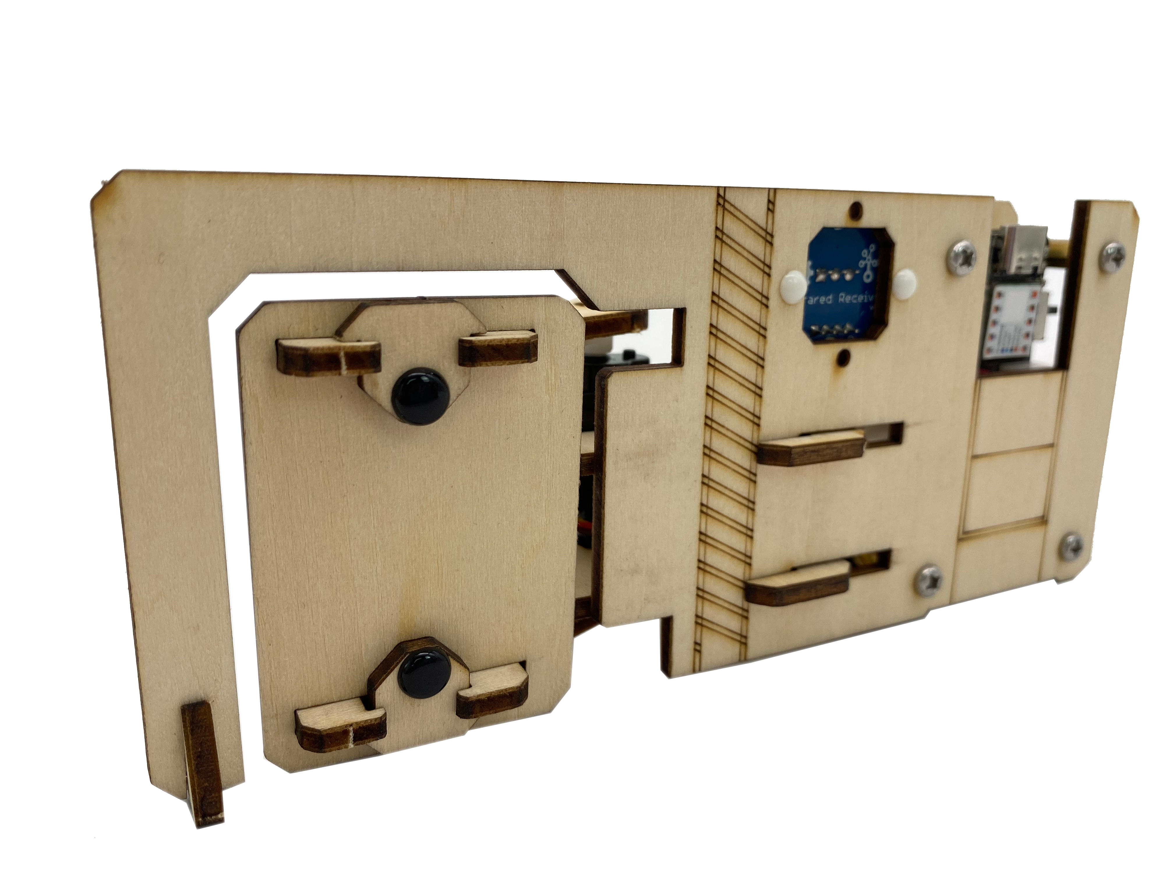
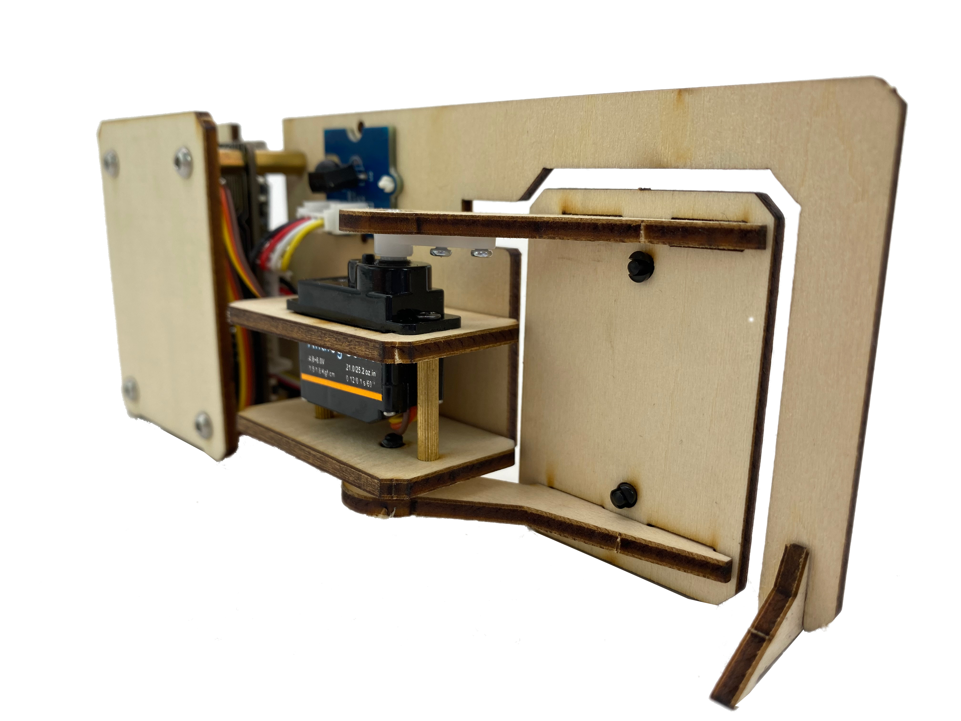
3.1.4 Exterior Design
In this unit, we need to implement a more complete project, combining the functions implemented by the program, the modules, and the appearance of the structure to form a prototype. Going back to the smart remote control door project, we need to control the rotation of the servo through the remote control, simulate the opening and closing of the door. When making the appearance, we need to focus on the following issues:
- How to combine the servo and the door panel to make the rotation of the servo drive the rotation of the door panel.
- The infrared receiver should be exposed in a conspicuous position, without any cover.
- Whether the main control, expansion board, and connecting wires are covered to keep the appearance neat.
- How to make the work stand steadily.
The figure below provides an appearance case, which is laser cut from basswood, and provides cutting files for reference. If you can use drawing software, you can process and design it yourself. If you don’t have a laser cutting machine, you can also use corrugated paper, cardstock, non-woven fabric, and other handmade materials to make it, which tests your hands-on ability more.
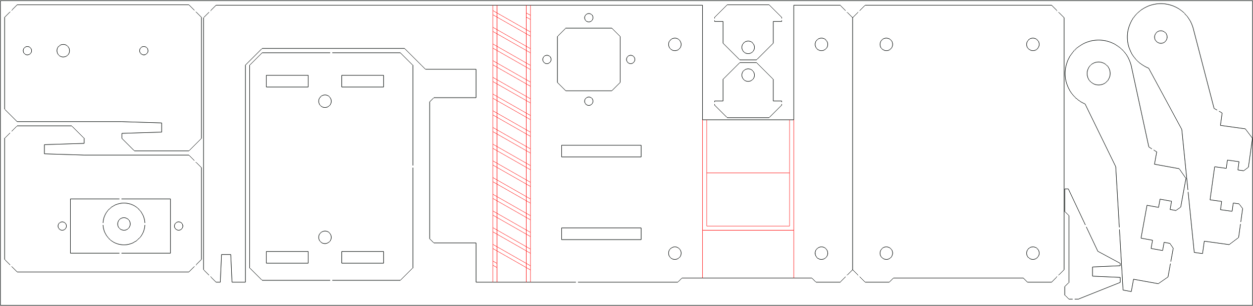
Download files for use with a laser cutter 🔗
https://github.com/mouseart/XIAO-Mastering-Arduino-and-TinyML/blob/main/dxf/XIAO_ADR.dxf.