2.3 Surprise Gift Box Based on Light Sensor
Are you thinking about gifting a special birthday present to your friend? Instead of buying one, you can create it with the modules we have at hand. In this section, we are going to create a surprise gift box for a good friend. What kind of surprise will appear when the gift box is opened? What kind of modules do we need to complete such a surprise gift box? Start today’s class with these questions.
2.3.1 Background Knowledge
2.3.1.1 Light Sensor
Light sensors can detect the light intensity in the surrounding environment and convert the detected light energy into electrical energy. Light sensors are divided into types such as photoresistive, photodiode, and photoelectric transistor. Here, we will simply introduce two commonly used light sensors, photoresistive and photodiode.
Photoresistive Type
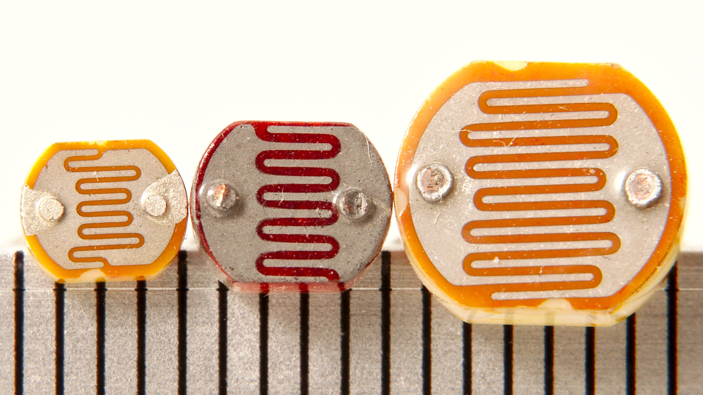
Firstly, the photoresistive type, its module will integrate a photoresistor, as shown below. The photoresistor is extremely sensitive to light, any light visible to our eyes can cause its reaction. High-intensity light will cause the resistance value to decrease, and low-intensity light will cause the resistance value to increase. By adjusting the resistance value in the circuit through the light intensity, it can control other devices, such as controlling the LED light on and off.
Photodiode Type
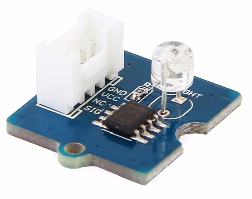
Photodiodes, also known as photoelectric sensors or photodetectors, when a beam of light hits the diode, the electrons in the tube will quickly scatter to form electron holes, thereby causing current to flow. The stronger the light, the stronger the current. Since the current generated by the photodiode is proportional to the intensity of light, it is very beneficial for light detection that requires a rapid change in light response. The light sensor we are going to use in this lesson is of this type.
Talking about the uses of light sensors, we can build a light-controlled switch through a light sensor, such as controlling the light on and off through a light sensor, turning off the light during the day, and turning on the light at night. The main purpose of the light control device is to save energy, improve efficiency through intelligent automation, the most common in life is probably the light control light, light control desk lamp, light control street lamp, highway tunnel lighting, etc., bringing convenience to our life and also contributing to environmental protection and energy conservation.
2.3.1.2 RGB LED Strip
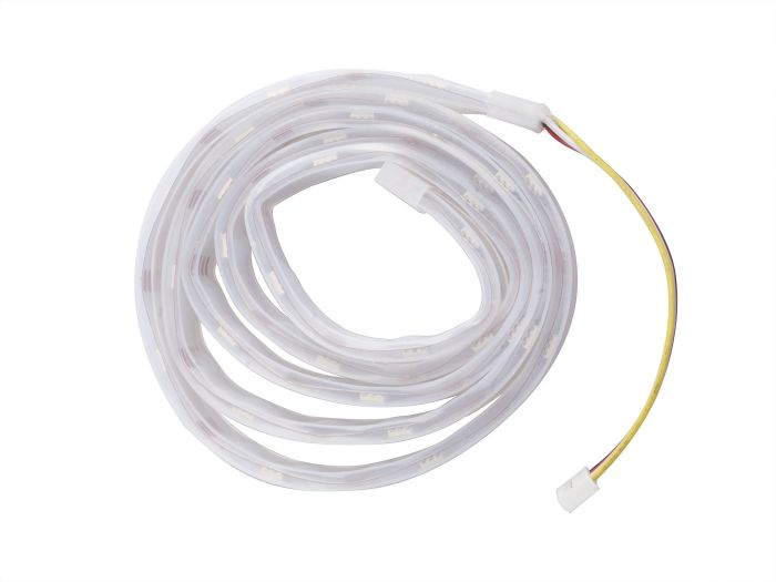
The project in this class is paired with an RGB LED strip. The strip integrates multiple color-adjustable light beads. Compared with a single LED, it can achieve more lighting effects and cool visual impacts, making it ideal for creating surprises. RGB LED strips come in various styles and models. The one we are going to use is the Grove - WS2813 RGB LED Strip, 30-bead model. We can control the RGB LED strip to achieve a rich lighting effect through programming, and build more interesting lighting projects.
2.3.2 Task 1: Light up RGB LED Strip To get started with RGB LED strips, start by installing and understanding its library.
Add the Adafruit_NeoPixel Library
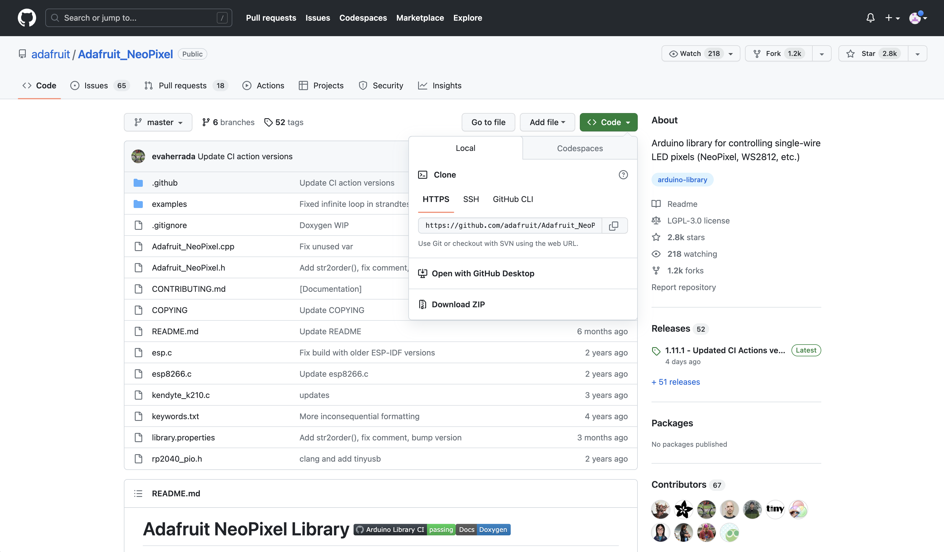
Before starting to program the RGB LED strip with the Arduino IDE, you need to add the necessary library files. Enter the library file address 🔗 https://github.com/adafruit/Adafruit_NeoPixel in the browser address bar, enter the GitHub page, click Code→Download ZIP to download the resource package Adafruit_NeoPixel-master.zip to your local machine.
Next, add the resource package Adafruit_NeoPixel-master.zip downloaded in the previous step via the menu bar Sketch→Include Library→Add .ZIP Library until you see the library loaded successfully.
Open the Simple Example
You can open the simple example through the following path: File → Examples → Adafruit NeoPixel → simple. Once the example program is opened, we can see the following program:
// NeoPixel Ring simple sketch (c) 2013 Shae Erisson
// Released under the GPLv3 license to match the rest of the
// Adafruit NeoPixel library

#include <Adafruit_NeoPixel.h>
#ifdef __AVR__
#include <avr/power.h> // Required for 16 MHz Adafruit Trinket
#endif

// Which pin on the Arduino is connected to the NeoPixels?
#define PIN        6 // On Trinket or Gemma, suggest changing this to 1

// How many NeoPixels are attached to the Arduino?
#define NUMPIXELS 16 // Popular NeoPixel ring size

// When setting up the NeoPixel library, we tell it how many pixels,
// and which pin to use to send signals. Note that for older NeoPixel
// strips you might need to change the third parameter -- see the
// strandtest example for more information on possible values.
Adafruit_NeoPixel pixels(NUMPIXELS, PIN, NEO_GRB + NEO_KHZ800);

#define DELAYVAL 500 // Time (in milliseconds) to pause between pixels

void setup() {
    // These lines are specifically to support the Adafruit Trinket 5V 16 MHz.
    // Any other board, you can remove this part (but no harm leaving it):
    #if defined(__AVR_ATtiny85__) && (F_CPU == 16000000)
    clock_prescale_set(clock_div_1);
    #endif
    // END of Trinket-specific code.

    pixels.begin(); // INITIALIZE NeoPixel strip object (REQUIRED)
}

void loop() {
    pixels.clear(); // Set all pixel colors to 'off'

    // The first NeoPixel in a strand is #0, second is 1, all the way up
    // to the count of pixels minus one.
    for(int i=0; i<NUMPIXELS; i++) { // For each pixel...

        // pixels.Color() takes RGB values, from 0,0,0 up to 255,255,255
        // Here we're using a moderately bright green color:
        pixels.setPixelColor(i, pixels.Color(0, 150, 0));

        pixels.show();   // Send the updated pixel colors to the hardware.

        delay(DELAYVAL); // Pause before next pass through loop
    }
}
This program allows the strip to light up 30 beads (green light) in sequence. This is a simple light strip example, and we need to modify some parameters:
#define PIN 0, you need to modify the pin connected to the light strip according to the actual situation. It is connected to the A0 interface of the XIAO expansion board, so it is PIN 0.
#define NUMPIXELS 30, defines the number of LEDs in the light strip. Since the light strip has different models and the number of integrated beads is different, we use a light strip with 30 beads, so it is NUMPIXELS 30.
After modifying the parameters, you can remove the English comments for a clearer view of the code. It occupies a large amount of space.
#include <Adafruit_NeoPixel.h> // Header file, declaring the library
#ifdef __AVR__
#include <avr/power.h>
#endif

#define PIN 0 // The light strip is connected to pin 0. If you are using XIAO RP2040, please change 0 to A0
#define NUMPIXELS 30 // The number of LED lights on the light strip
Adafruit_NeoPixel pixels(NUMPIXELS, PIN, NEO_GRB + NEO_KHZ800); // Create a new light strip object, define data mode
#define DELAYVAL 500 // The interval time for each light to light up

void setup() {
    #if defined(__AVR_ATtiny85__) && (F_CPU == 16000000)
    clock_prescale_set(clock_div_1);
    #endif
    pixels.begin(); // The light strip is ready to output data
}

void loop() {
    pixels.clear(); // All beads on the light strip are turned off
    for(int i=0; i<NUMPIXELS; i++) {
        pixels.setPixelColor(i, pixels.Color(0, 150, 0)); // Light up the beads in sequence, the color is green
        pixels.show(); // Display the light strip
        delay(DELAYVAL);
    }
}
Get this program from Github
https://github.com/mouseart/XIAO-Mastering-Arduino-and-TinyML/tree/main/code/L9_NeoPixel30_simple_XIAO_en
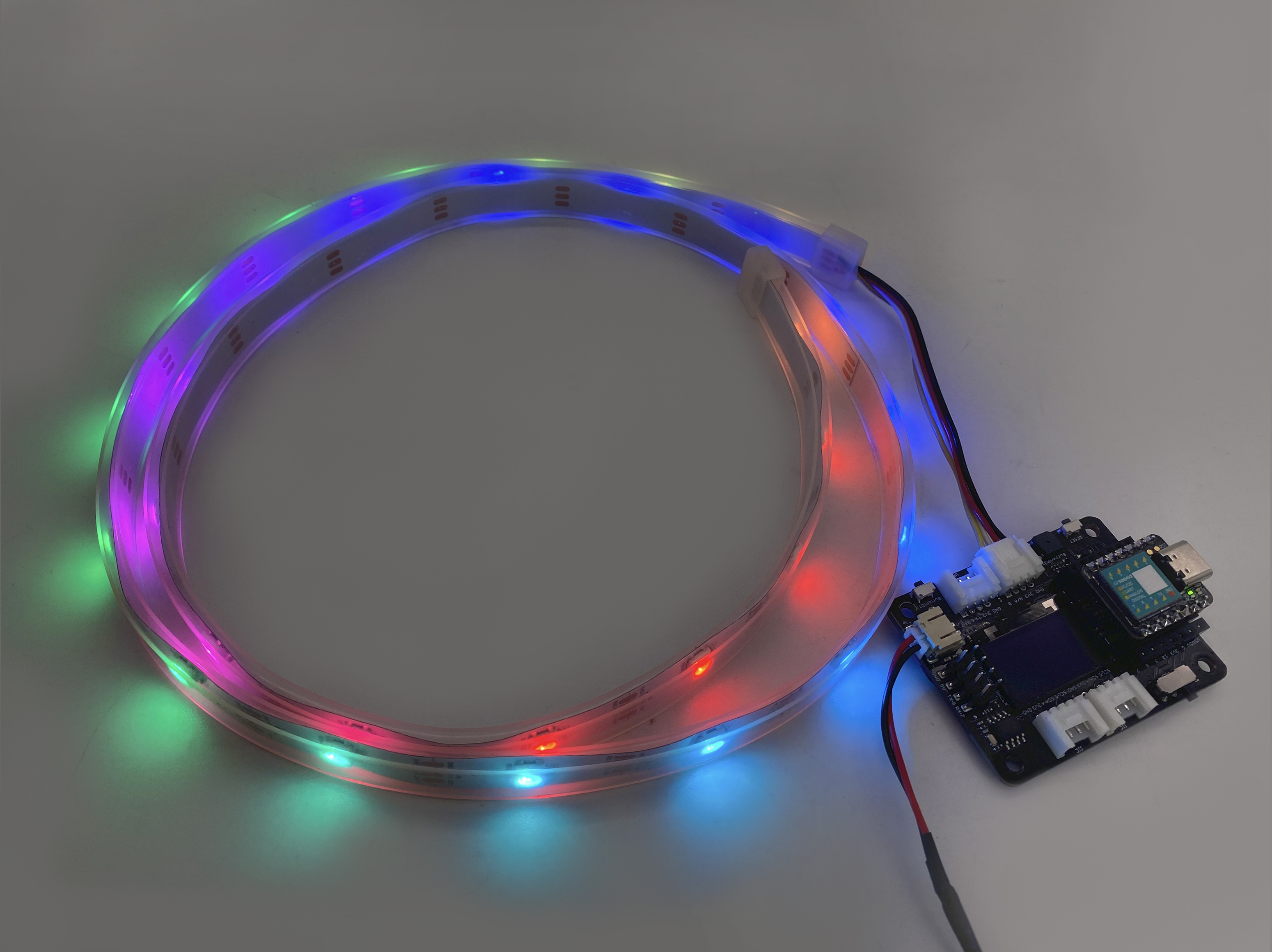
In the code above, pixels.Color(0,150,0) is a function to set the color of the LED light strip. The numbers in the parentheses represent the three primary colors (red, green, blue) respectively. If it is (0,150,0), it means that the brightness of red is 0, the brightness of green is 150, and the brightness of blue is 0. The entire light strip will show a green effect. The larger the number, the brighter it will be, with a maximum of 255. Next, connect the light strip to the A0/D0 interface of the XIAO expansion board, as shown in the following figure:

Connect the XIAO main board to the computer with a data cable, and upload the program to the main board. After the upload is successful, observe the effect of the light strip.
The light strip can change color, flicker, and present various lighting effects such as breathing. We can refer to the sample program in the library: File → Example → Adafruit NeoPixel → buttoncycler. This sample program switches different lighting effects on the light strip through buttons. We can find the code for various lighting effects in it, such as flickering, rainbow lights, chasing, etc.
2.3.3 Project Making: Surprise Gift Box
Project Description
The program for the surprise gift box wants to realize: Use a light sensor to control the on and off of the RGB LED light strip, just like a light-controlled lamp, but the effect is opposite. When the value detected by the light sensor is less than a fixed value, that is, it is in a dim environment, the RGB LED light strip is off. When the value detected by the light sensor is greater than a fixed value, that is, in a bright environment, the RGB LED light strip lights up the rainbow light.
Program Writing
The program writing idea is as follows:
- Declare the files to be called, create a new light strip object, define the sensor pin and the number of LEDs on the light strip.
- Initialize the light strip and set the light sensor pin mode.
- Read the light value. If the light value is greater than 100, the light strip will present a rainbow and breathing light effect. Otherwise, the light strip will turn off.
The program is completed in two tasks:
Task 1: Make the Light Strip Present Rainbow and Breathing Light Effect
Step 1: Declare the files to be called, declare the light strip object, and define the pin and the number of LEDs on the light strip.
#include <Adafruit_NeoPixel.h> // Header file, declaring the library
#ifdef __AVR__
#include <avr/power.h>
#endif

#define PIXEL_PIN 0 // The light strip is connected to pin A0. If you are using XIAO RP2040, please change 0 to A0
#define PIXEL_COUNT 30 // The number of LED lights on the light strip
Adafruit_NeoPixel strip(PIXEL_COUNT, PIXEL_PIN, NEO_GRB + NEO_KHZ800);
// Declare a new light strip object and define the data mode
Step 2: Initialize the light strip.
void setup() {
    strip.begin(); // Initialize the light strip, the light strip is ready to output data
}
Step 3: The light strip presents a rainbow and breathing light effect. This part uses the for() function to present the breathing effect. For example, for( i = 0; i<5; i ++ ){} means that the initial value of i is 0, when i is less than 5, the statement in the loop body {} is run, each time the loop is run, i is incremented by 1. This loop will run 5 times.
void loop() {
    strip.clear();// Turn off all the lights on the light strip
    rainbow(10);// The light strip displays a rainbow light effect. The number in the parenthesis represents the speed of the rainbow light circulation. The smaller the number, the faster the circulation speed
}
// The following is the code for the rainbow light effect, presenting the breathing light effect. This code can be found in the example program buttoncycler
void rainbow(int wait) {
    for(long firstPixelHue = 0; firstPixelHue < 3*65536; firstPixelHue += 256) {
        for(int i=0; i<strip.numPixels(); i++) {
            int pixelHue = firstPixelHue + (i * 65536L / strip.numPixels());
            strip.setPixelColor(i, strip.gamma32(strip.ColorHSV(pixelHue)));
        }
        strip.show(); // The light strip presents a light effect
        delay(wait);  // Delay
    }
}
Get this program from Github
https://github.com/mouseart/XIAO-Mastering-Arduino-and-TinyML/tree/main/code/L9_Rainbow_XIAO_en
Step 4: Connect the hardware and upload the program. First, connect the RGB LED light strip to the A0/D0 interface of the XIAO expansion board, as shown in the figure:
Use a data cable to connect XIAO to the computer, click the “Upload” button, and upload the program to the hardware. When the debugging area shows “Upload successful”, you can observe the light effect of the light strip.
Task 2: Adding Light Control Switch Function
Step 1: Add code.
The added function is mainly to read the light value detected by the light sensor, and use the if…else… statement to judge the light value. When it is greater than 100 (this value can be adjusted according to the actual environment), the RGB LED light strip will show a rainbow breathing light effect.
Part of the program added:
// This is an added part of the program, it cannot run directly
#define LIGHT_PIN 7// Define the light sensor connected to A7. If you are using XIAO RP2040, please change 7 to A3. If you are using XIAO BLE, please change 7 to 5
#define PIXEL_PIN 0// Define light strip. If you are using XIAO RP2040, please change 0 to A0
int readValue = 0;// Define the variable readValue to store the light value
void setup() {
    pinMode(LIGHT_PIN , INPUT); // Set the pin of the light sensor as input status
}
void loop() {
    readValue = analogRead(A7);// Read the analog value of the A7 pin light and store it in the readValue variable. If you are using XIAO RP2040, please change A7 to A3. If you are using XIAO BLE, please change A7 to A5
    if(readValue > 500){ // Condition judgment, if the light value is greater than 500, then the light strip presents a rainbow light effect, otherwise, the light strip is turned off
        rainbow(10);
    }else {
        strip.clear();
        strip.show();
    }
}
We add the entered statement to the corresponding position of Task 1’s program. See the complete program:
#include <Adafruit_NeoPixel.h>// Header file, declare library
#ifdef __AVR__
#include <avr/power.h>
#endif
#define LIGHT_PIN 7// Define the light sensor connected to A7. If you are using XIAO RP2040, please change 7 to A3. If you are using XIAO BLE, please change 7 to 5
#define PIXEL_PIN 0 // The light strip is connected to the A0 pin. If you are using XIAO RP2040, please change 0 to A0
#define PIXEL_COUNT 30 // The number of LEDs on the light strip
int readValue = 0;// Define variable readValue to store light values
Adafruit_NeoPixel strip(PIXEL_COUNT, PIXEL_PIN, NEO_GRB + NEO_KHZ800);
// Declare the light strip object and define the data mode
void setup() {
  strip.begin(); // Initialize the light strip and prepare the light strip to output data
  pinMode(LIGHT_PIN , INPUT); // Set the pin of the light sensor to input state
}
void loop() {
  strip.clear();// Turn off all the beads on the light strip
  rainbow(10);// The light strip shows a rainbow light effect. The number in the parentheses represents the speed of the rainbow light rotation. The smaller the number, the faster the rotation speed
  readValue = analogRead(A7);// Read the analog value of the light on the A7 pin and store it in the readValue variable. If you are using XIAO RP2040, please change A7 to A3. If you are using XIAO BLE, please change A7 to A5
    if(readValue > 500){ // Conditional judgment, if the light value is greater than 500, then the light strip presents a rainbow light effect, otherwise, the light strip is turned off
        rainbow(10);
    }else {
        strip.clear();
        strip.show();
    }
}
// The following is the code for the rainbow light effect, presenting the breathing light effect, this code can be found in the sample program buttoncycler
void rainbow(int wait) {
  for(long firstPixelHue = 0; firstPixelHue < 3*65536; firstPixelHue += 256) {
    for(int i=0; i<strip.numPixels(); i++) {
      int pixelHue = firstPixelHue + (i * 65536L / strip.numPixels());
      strip.setPixelColor(i, strip.gamma32(strip.ColorHSV(pixelHue)));
    }
    strip.show(); // The light strip presents a light effect
    delay(wait);  // Delay
  }
}
Get this program from Github
https://github.com/mouseart/XIAO-Mastering-Arduino-and-TinyML/tree/main/code/L9_StripLight_XIAO_en
Step 2: Connect the hardware and upload the program. First, connect the RGB LED light strip to the A0 interface of the XIAO expansion board, and connect the light sensor to the A7 interface, as shown in the figure below:
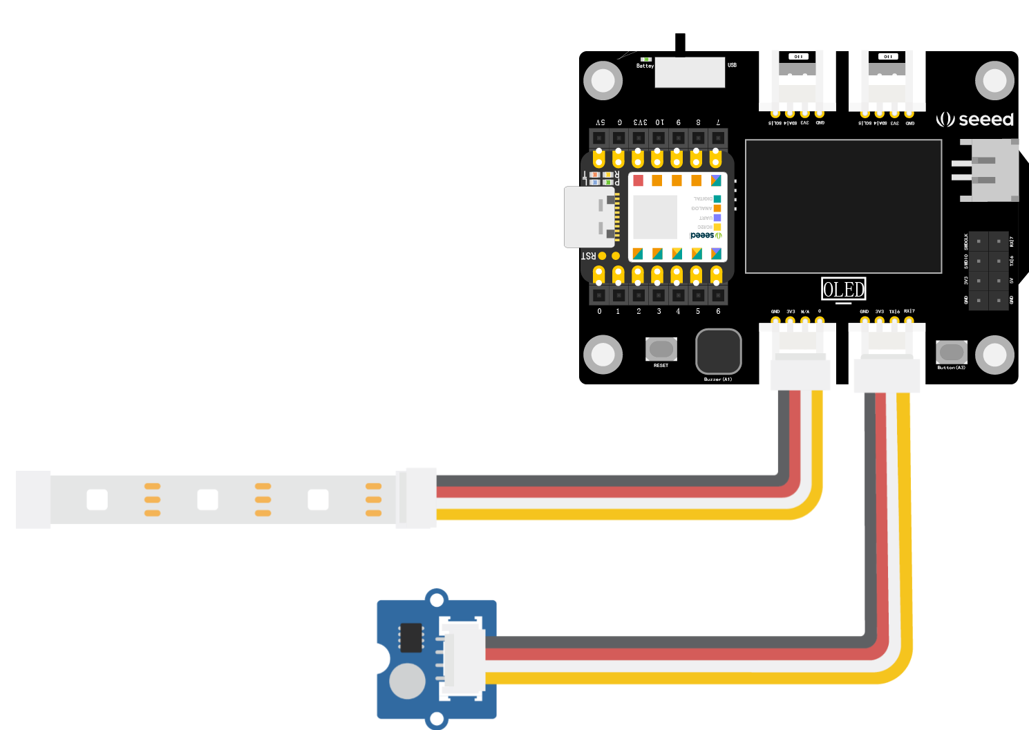
⚠️ Note
If you are using XIAO BLE, please connect the light sensor to the I2C interface of the XIAO expansion board.
If you are using XIAO RP2040, due to the limited number of pins exposed, you need to connect the SIG pin of the light sensor and theA3pin of XIAO RP2040 with Dupont wires on your own.
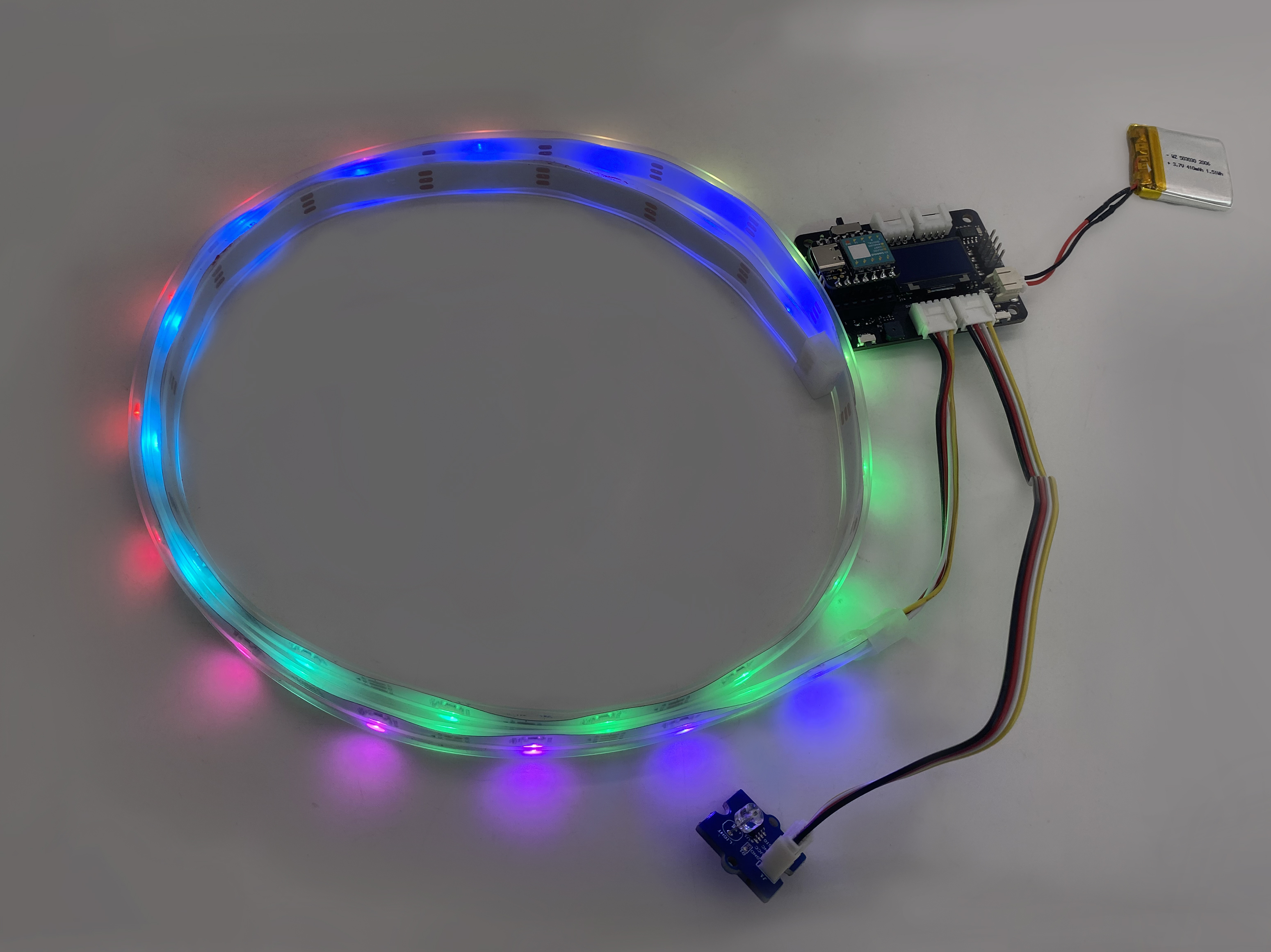
Next, connect XIAO to your computer with a data cable, click the “Upload” button in the Arduino IDE to upload the program to the hardware. When the debugging area shows “Upload successful”, you can cover the light sensor with your hand, then release the light sensor, and observe the changes in the light strip. Note that because it takes a certain amount of time for the light strip to display light effects, the light strip will not turn off immediately when you cover the light sensor.
2.3.4 Exterior Design
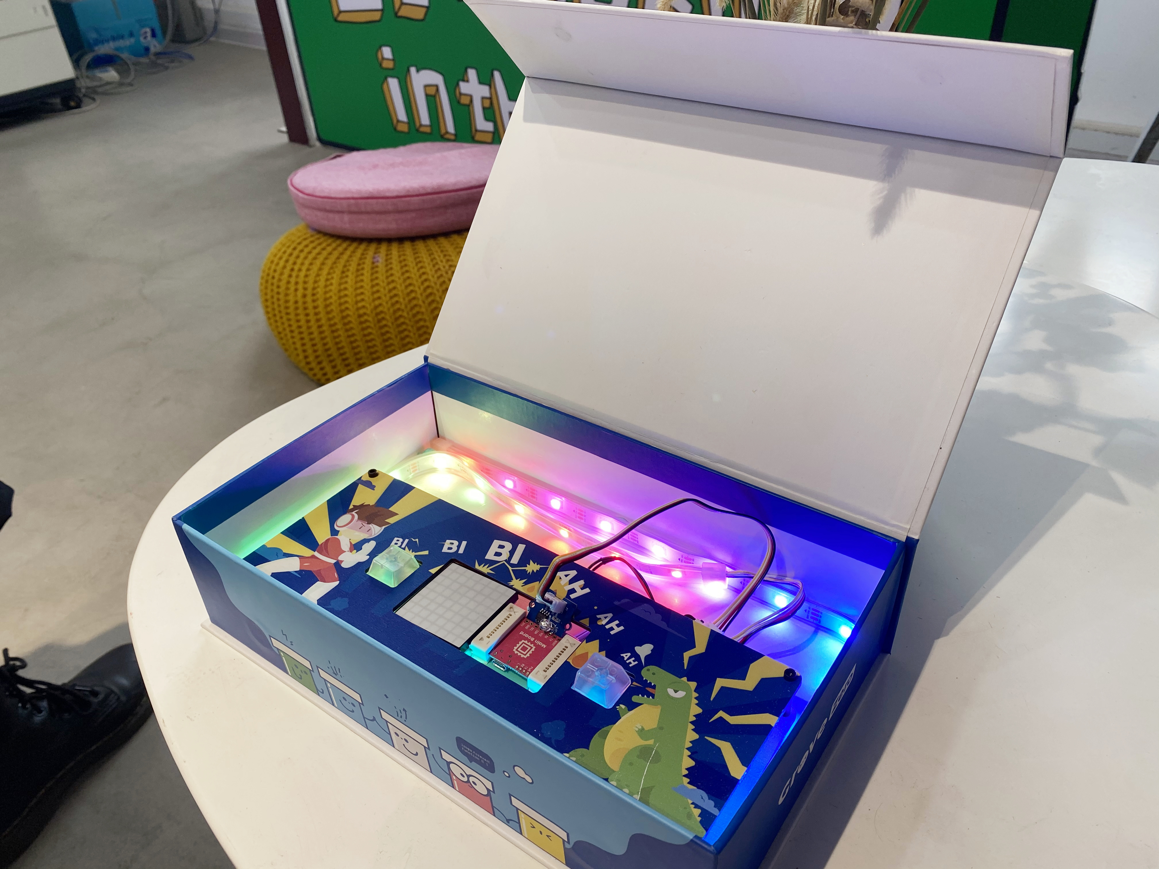
Combining the program design of the surprise gift box, when the light sensor is in a dim environment, the RGB LED light strip is off, and when the light sensor is in a bright environment, the RGB LED light strip lights up with rainbow lights. We can imagine that the electronic part is placed in a closed box, which can match the function implemented by the program and can also meet the positioning of the gift. Of course, you can also have other designs.
| Product Name | Surprise Gift Box |
|---|---|
| Product Features | Cool light effects, photocontrol, surprise, birthday |
| Product Functions | Control the lighting of the RGB LED light strip with a light sensor |
| Product Appearance |
Case reference