1.5 Controlling LED and Servo with a Knob
In the last section, we learned how to use the serial monitor and observed the differences between digital input and analog input through it. In this section, we will further explore the use of analog values by combining them with a rotary potentiometer!
1.5.1 Background Knowledge
1.5.1.1 Servo and Servo Library
Servo

A servo, also known as a servo motor, is a DC motor with gears and a feedback system. We can control the servo to rotate to a specific angular position by sending signals to the circuit. This makes it suitable for electronic devices or robots that require precise position control.
Servo Library servo.h
When we want to control a servo using XIAO or other Arduino development boards, we can use the servo.h library file. It’s one of the Arduino standard libraries, which is convenient to use and also avoids the problem of limited PWM pin quantity. Here are the relevant functions of the servo library:
Declare the library file
#include <Servo.h>Create the
myservoobject to control the servo
Servo myservo;Use the
attach()function to call the signal pin
myservo.attach();Use the
write()function to write the angle to the servo, setting the rotation angle of the shaft
myservo.write();
The servo library does not need to be manually installed. You can open the example program “File → Examples → Servo” and check the two example programs “Knob” and “Sweep” to familiarize yourself with the use of the servo library.

If you can’t find Servo under Examples, you can visit https://github.com/arduino-libraries/Servo and add the Servo example by installing the library.
1.5.1.2 map() Function
The map() function is used to map a number from one range to another. That is, fromLow gets mapped to toLow, and fromHigh gets mapped to toHigh. It’s the simplest form of linear mapping.
Syntax
map(value, fromLow, fromHigh, toLow, toHigh)
Parameters
value: The number to be mapped.
fromLow: The lower limit of the current range of the value.
fromHigh: The upper limit of the current range of the value.
toLow: The lower limit of the target range of the value.
toHigh: The upper limit of the target range of the value.
Example: Map val from the range 0-1023 to 0-255.
void setup() {}
void loop() {
    int val = analogRead(0); // read the value from analog pin A0
    val = map(val, 0, 1023, 0, 255); // map val to the range 0-255
    analogWrite(9, val); // output the analog value to pin 9
}
1.5.2 Task 1: Using a knob potentiometer to control the brightness of the onboard LED on the XIAO board
Analysis:
When using a knob potentiometer to control the LED, we need to use the map() function, because the analog value directly output by the knob potentiometer is 0-1023, this value is not the angle value of the knob rotation, we need to calculate the angle value of the knob potentiometer rotation first, then map this value to the brightness range of the LED 0-255 with the map() function. The steps to write the program are as follows:
- Define the knob potentiometer, LED pin.
- Initialize the serial port, set the status of the knob potentiometer and LED pin.
- Read and calculate the rotation angle value of the knob potentiometer, and send it to the serial port.
- Map the angle value of the knob potentiometer to the LED brightness value and store it in the brightness variable, and the LED outputs this variable value.
Writing the program:
Step 1: Define the knob potentiometer, LED pin, here we need to define ADC and VCC reference voltage, in order to calculate the angle value of the knob potentiometer.
#define ROTARY_ANGLE_SENSOR A0 //Define rotary potentiometer interface A0
#define LEDPIN 13 //Define LED interface 13
#define ADC_REF 3 //Reference voltage 3V
#define GROVE_VCC 3 //GROVE reference voltage 3V
#define FULL_ANGLE 300 //The maximum rotation angle of the rotary potentiometer is 300°
Step 2: Initialize the serial port, set the status of the knob potentiometer and LED pin.
void setup()
{
    Serial.begin(9600); //Initialize serial communication
    pinMode(ROTARY_ANGLE_SENSOR, INPUT); //Set the rotary potentiometer pin to input
    pinMode(LEDPIN,OUTPUT); //Set the LED pin to output
}
Step 3: Read and calculate the rotation angle value of the knob potentiometer, and send it to the serial port.
void loop()
{
    float voltage; //Variable voltage of type float
    int sensor_value = analogRead(ROTARY_ANGLE_SENSOR); //Read the analog value at the rotary potentiometer pin
    voltage = (float)sensor_value*ADC_REF/1023; //Calculate the real-time voltage
    float degrees = (voltage*FULL_ANGLE)/GROVE_VCC; //Calculate the angle of rotation of the knob
    Serial.println("The angle between the mark and the starting position:"); //Print character on serial monitor
    Serial.println(degrees); //Print the rotation angle value of the rotary potentiometer on the serial monitor
    delay(100);
Step 4: Map the angle value of the knob potentiometer to the LED brightness value and store it in the brightness variable, and the LED outputs this variable value.
//After Step 3
    int brightness; //Define brightness variable
    brightness = map(degrees, 0, FULL_ANGLE, 0, 255); //Map the rotation angle value of the rotary potentiometer to the brightness value of the LED and store it in the brightness variable
    analogWrite(LEDPIN,brightness); //Output the variable value to the LED
    delay(500);
}
The final complete code is shown below:
#define ROTARY_ANGLE_SENSOR A0 //Define rotary potentiometer interface A0
#define LEDPIN 13 //Define LED interface 13
#define ADC_REF 3 //Reference voltage 3V
#define GROVE_VCC 3 //GROVE reference voltage 3V
#define FULL_ANGLE 300 //The maximum rotation angle of the rotary potentiometer is 300°

void setup()
{
    Serial.begin(9600); //Initialize serial communication
    pinMode(ROTARY_ANGLE_SENSOR, INPUT); //Set the rotary potentiometer pin to input
    pinMode(LEDPIN,OUTPUT); //Set the LED pin to output
}

void loop()
{
    float voltage; //Variable voltage of type float
    int sensor_value = analogRead(ROTARY_ANGLE_SENSOR); //Read the analog value at the rotary potentiometer pin
    voltage = (float)sensor_value*ADC_REF/1023; //Calculate the real-time voltage
    float degrees = (voltage*FULL_ANGLE)/GROVE_VCC; //Calculate the angle of rotation of the knob
    Serial.println("The angle between the mark and the starting position:"); //Print character on serial monitor
    Serial.println(degrees); //Print the rotation angle value of the rotary potentiometer on the serial monitor
    delay(100);

    int brightness; //Define brightness variable
    brightness = map(degrees, 0, FULL_ANGLE, 0, 255); //Map the rotation angle value of the rotary potentiometer to the brightness value of the LED and store it in the brightness variable
    analogWrite(LEDPIN,brightness); //Output the variable value to the LED
    delay(500);
}
Get this program from Github
https://github.com/mouseart/XIAO-Mastering-Arduino-and-TinyML/tree/main/code/L5_RotaryLed_XIAO_en
Uploading the Program:
After writing the program, connect the rotary potentiometer to the A0 interface using a four-color Grove wire, as shown in the following figure:

Connect the XIAO main control board to your computer with a data cable. After connecting, click ![]() (the verify button) in the Arduino IDE to check the program. If there are no errors, click
(the verify button) in the Arduino IDE to check the program. If there are no errors, click ![]() (the upload button) to upload the program to the hardware. When the debug area shows “Done uploading.”, you can open the serial monitor to observe the rotation angle and LED brightness values as you rotate the potentiometer.
(the upload button) to upload the program to the hardware. When the debug area shows “Done uploading.”, you can open the serial monitor to observe the rotation angle and LED brightness values as you rotate the potentiometer.

⚠️ Note
The onboard LED of the XIAO board is used in this example.
If you need to operate offline, you can connect a lithium battery to the expansion board, as shown in the following figure.

Controlling an External LED with a Knob on the XIAO ESP32C3
The Seeed XIAO ESP32C3 does not have an onboard LED for users. To run this program, you need to first connect an LED to the D10 pin of the board, as shown below:
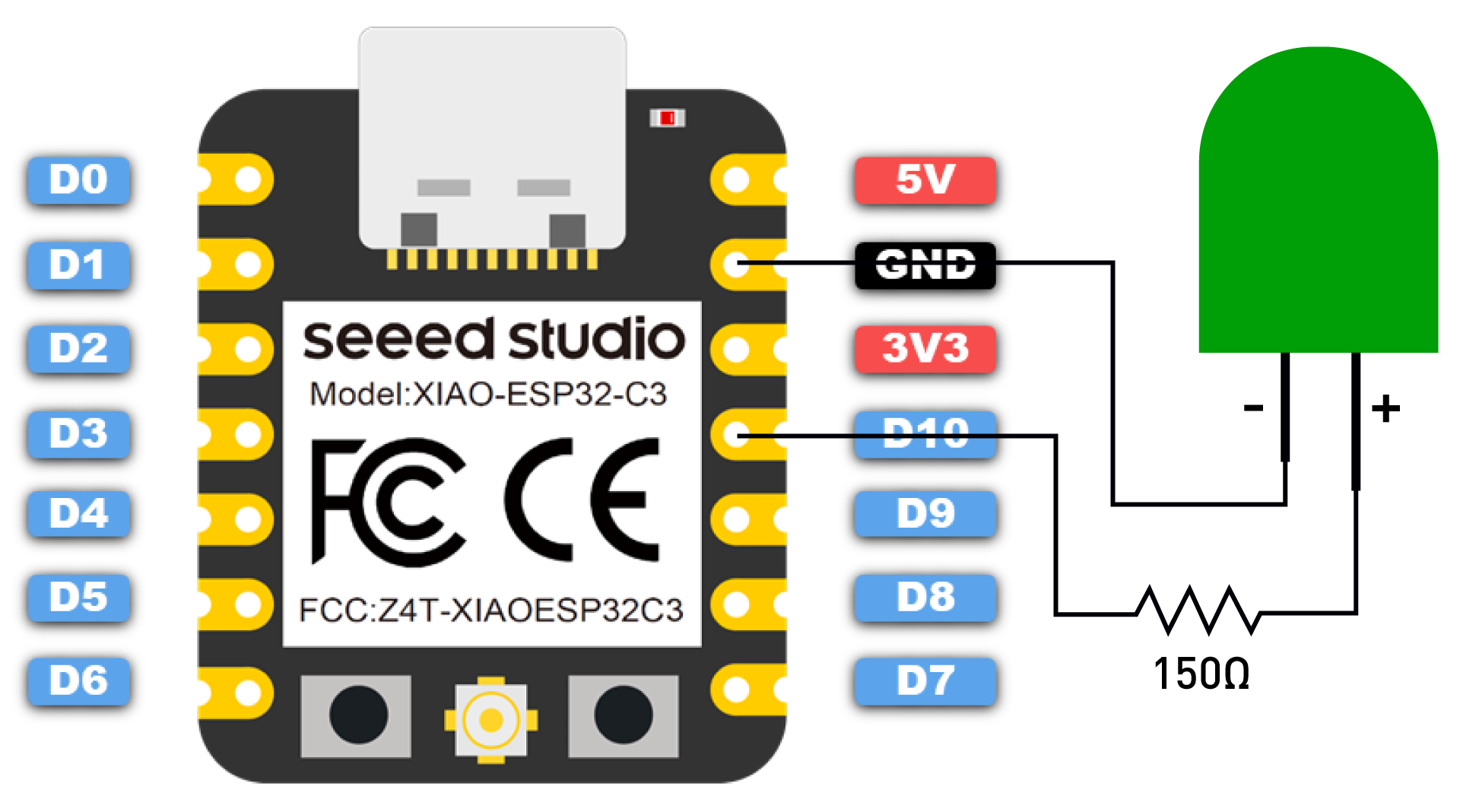
⚠️ Note
Be sure to connect a resistor (about 150Ω) in series with the LED to limit the current passing through the LED and prevent it from being damaged by overcurrent.
Next, copy the following program into the Arduino IDE:
#define ROTARY_ANGLE_SENSOR A0 // Define rotary potentiometer interface A0
#define LEDPIN D10 // Define LED light interface 10
#define ADC_REF 3 // Reference voltage 3V
#define GROVE_VCC 3 // GROVE reference voltage 3V
#define FULL_ANGLE 300 // The maximum rotation angle of the rotary potentiometer is 300°

void setup()
{
    Serial.begin(9600); // Initialize serial communication
    pinMode(ROTARY_ANGLE_SENSOR, INPUT); // Set the rotary potentiometer pin to input mode
    pinMode(LEDPIN, OUTPUT); // Set the LED light pin to output mode
}

void loop()
{
    float voltage; // Define voltage variable as float
    int sensor_value = analogRead(ROTARY_ANGLE_SENSOR); // Read the analog value on the rotary potentiometer pin
    voltage = (float)sensor_value*ADC_REF/1023; // Calculate real-time voltage
    float degrees = (voltage*FULL_ANGLE)/GROVE_VCC; // Calculate the angle of rotation of the knob
    Serial.println("The angle between the mark and the starting position:"); // Print string to serial port
    Serial.println(degrees); // Print the rotation angle value of the rotary potentiometer to the serial port
    delay(100);

    int brightness; // Define brightness variable
    brightness = map(degrees, 0, FULL_ANGLE, 0, 255); // Map the rotary potentiometer angle value to LED light brightness value and store it in the brightness variable
    analogWrite(LEDPIN, brightness); // Output brightness value to LED light
    delay(500);
}
Get this program from Github
https://github.com/mouseart/XIAO-Mastering-Arduino-and-TinyML/tree/main/code/L5_RotaryLed_XIAO_ESP32C3_en
1.5.3 Task 2: Control a Servo Motor with a Rotary Potentiometer
Analysis
When controlling a servo motor with a rotary potentiometer, we can use the servo.h library and modify our first task slightly. The program can be divided into the following steps:
- Declare the servo library, define the servo rotation angle variable, define the rotary potentiometer pin and voltage.
- Initialize the serial port, set the status of the rotary potentiometer and servo pins.
- Read and calculate the rotation angle value of the rotary potentiometer, send it to the serial port, and drive the servo to rotate according to the angle value change.
Program Writing
Step 1: Declare the servo library, define the servo rotation angle variable, define the rotary potentiometer pin and voltage.
#include <Servo.h>// Declare the use of the servo library
#define ROTARY_ANGLE_SENSOR A0 // Define the rotary potentiometer pin as A0
#define ADC_REF 3 // ADC reference voltage is 3V
#define GROVE_VCC 3 // GROVE module reference voltage is 3V
#define FULL_ANGLE 300 // The maximum rotation angle of the rotary potentiometer is 300°
Servo myservo;  // Create a myservo object to control the servo
int pos = 0; // Variable to store the rotation angle of the servo
Step 2: Initialize the serial port, set the status of the rotary potentiometer and servo pins.
void setup() {
    Serial.begin(9600);// Initialize the serial port
    pinMode(ROTARY_ANGLE_SENSOR, INPUT);// Set the rotary potentiometer pin as input
    myservo.attach(5);  // The myservo signal is transmitted through pin 5, if you are using XIAO RP2040/XIAO ESP32, please modify 5 to D5
}
Step 3: Read and calculate the rotation angle value of the rotary potentiometer, send it to the serial port, and drive the servo to rotate according to the angle value change.
void loop() {
    float voltage;// Set voltage as a floating point
    int sensor_value = analogRead(ROTARY_ANGLE_SENSOR);// Read the analog value at the rotary potentiometer pin
    voltage = (float)sensor_value * ADC_REF / 1023;// Real-time voltage is the read analog value multiplied by the reference voltage divided by 1023
    float degrees = (voltage * FULL_ANGLE) / GROVE_VCC;// The rotation angle of the knob is the real-time voltage multiplied by the maximum rotation angle of the rotary potentiometer divided by the voltage value of the GROVE module interface
    Serial.println("The angle between the mark and the starting position:");// Print characters on the serial port
    Serial.println(degrees);// Print the rotation angle value of the rotary potentiometer on the serial port
    delay(50);
    myservo.write(degrees); // Write the rotation angle value of the rotary potentiometer into the servo
}
The final code is as follows:
#include <Servo.h>// Declare the use of the servo library
#define ROTARY_ANGLE_SENSOR A0 // Define the rotary potentiometer pin as A0
#define ADC_REF 3 // ADC reference voltage is 3V
#define GROVE_VCC 3 // GROVE module reference voltage is 3V
#define FULL_ANGLE 300 // The maximum rotation angle of the rotary potentiometer is 300°
Servo myservo;  // Create a myservo object to control the servo
int pos = 0; // Variable to store the rotation angle of the servo

void setup() {
    Serial.begin(9600);// Initialize the serial port
    pinMode(ROTARY_ANGLE_SENSOR, INPUT);// Set the rotary potentiometer pin as input
    myservo.attach(5);  // The myservo signal is transmitted through pin 5, if you are using XIAO RP2040/XIAO ESP32, please modify 5 to D5
}

void loop() {
    float voltage;// Set voltage as a floating point
    int sensor_value = analogRead(ROTARY_ANGLE_SENSOR);// Read the analog value at the rotary potentiometer pin
    voltage = (float)sensor_value * ADC_REF / 1023;// Real-time voltage is the read analog value multiplied by the reference voltage divided by 1023
    float degrees = (voltage * FULL_ANGLE) / GROVE_VCC;// The rotation angle of the knob is the real-time voltage multiplied by the maximum rotation angle of the rotary potentiometer divided by the voltage value of the GROVE module interface
    Serial.println("The angle between the mark and the starting position:");// Print characters on the serial port
    Serial.println(degrees);// Print the rotation angle value of the rotary potentiometer on the serial port
    delay(50);
    myservo.write(degrees); // Write the rotation angle value of the rotary potentiometer into the servo
}
Get this program from Github
https://github.com/mouseart/XIAO-Mastering-Arduino-and-TinyML/tree/main/code/L5_RotaryServo_XIAO_en
Upload Program
After writing the program, first connect the knob potentiometer and the servo to the XIAO expansion board as shown in the figure below. Then, connect the XIAO main control board to the computer with a data cable.

After the connection, click ![]() (the verify button) in the Arduino IDE to verify the program. If the verification is error-free, click
(the verify button) in the Arduino IDE to verify the program. If the verification is error-free, click ![]() (the upload button) to upload the program to the hardware. When the debugging area shows “Done uploading.”, you can open the serial monitor, rotate the knob potentiometer, and observe the changes in angle value and the movement of the servo. What have you found?
(the upload button) to upload the program to the hardware. When the debugging area shows “Done uploading.”, you can open the serial monitor, rotate the knob potentiometer, and observe the changes in angle value and the movement of the servo. What have you found?

⚠️ Note
The rotation range of the servo is 0°-180°, so you will see in the serial monitor that when the angle value is greater than 180°, the servo stops rotating.
1.5.4 Extended Exercise
We have been using the LED on the XIAO board. If I want to use an external LED and control it with a knob potentiometer to create a breathing light effect, what should I do? The XIAO expansion board brings out two digital-analog Grove interfaces, and there is an A7/D7 interface. We can connect the external LED to this interface, as shown in the figure:

After the connection, we can slightly modify the program from Task 1, changing #define LEDPIN 13 to #define LEDPIN 7. Upload the modified program and see if it can achieve our desired effect.
Get this program from Github
https://github.com/mouseart/XIAO-Mastering-Arduino-and-TinyML/tree/main/code/L5_RotaryLed_ledmodule_en