1.2 Using the Button Switch on the XIAO Expansion Board to Control an LED Light
In the previous section, we learned how to control an LED light to blink using only the Seeed Studio XIAO and the onboard LED light. However, there was no interaction with the external environment, such as controlling the LED light through light or sound. In this section, we will introduce a simple sensor - the button switch, to form an automatic control system of sensor-controller-actuator. Before starting the task, we need to learn some basic knowledge, like what variables are and the common program structures, so that we can better understand and run the program.
1.2.1 Background Knowledge
In the last section, we only used the onboard LED light of the Seeed Studio XIAO without connecting other modules. It could take quite some effort for beginners to use Dupont wires to connect external sensors to a board the size of a thumb and also involve a breadboard. Is there a simpler method?
1.2.1.1 Seeed Studio XIAO Expansion Board
The Seeed Studio XIAO Expansion Board, only half the size of Raspberry Pi 4, is powerful and can quickly and easily build prototypes and projects. The board has a variety of peripherals such as OLED, RTC, expandable memory, passive buzzer, RESET/User button, 5V servo/sensor connector, various data interfaces… You can explore the infinite possibilities of Seeed Studio XIAO. The board also supports CircuitPython.
All models in the Seeed Studio XIAO series have uniform specifications and support the Seeed Studio XIAO Grove Shield and Seeed Studio XIAO Expansion Board. The series includes XIAO SAMD21, XIAO RP2040, XIAO nRF52840, XIAO nRF52840 Sense, XIAO ESP32C3 and XIAO ESP32S3. The front and back function interfaces of the XIAO expansion board are shown in the following figure:
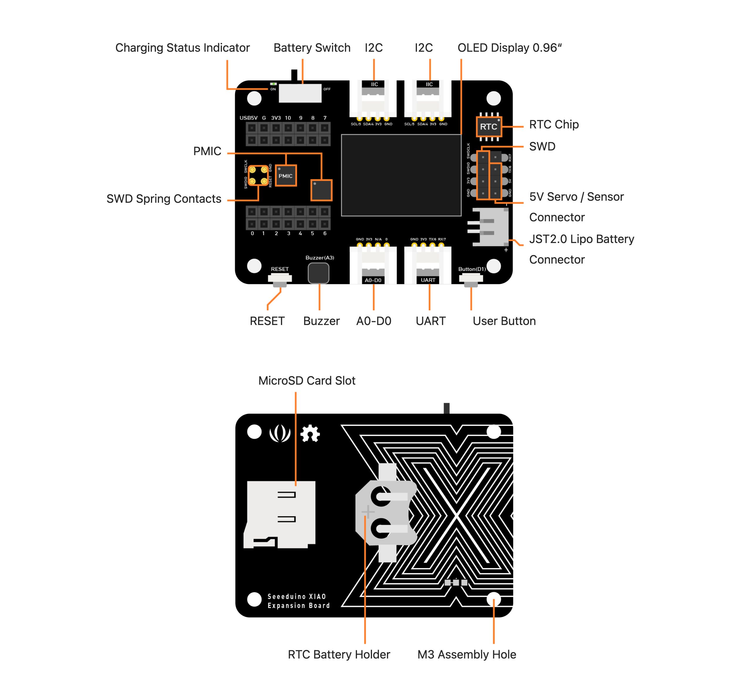
To make it easier and quicker to build projects with Seeed Studio XIAO, we equipped it with a powerful expansion board. This board has a wealth of onboard peripherals and can quickly connect to more electronic modules to implement various functions. The expansion board brings out all the pins of XIAO, as shown in the pin diagram below:
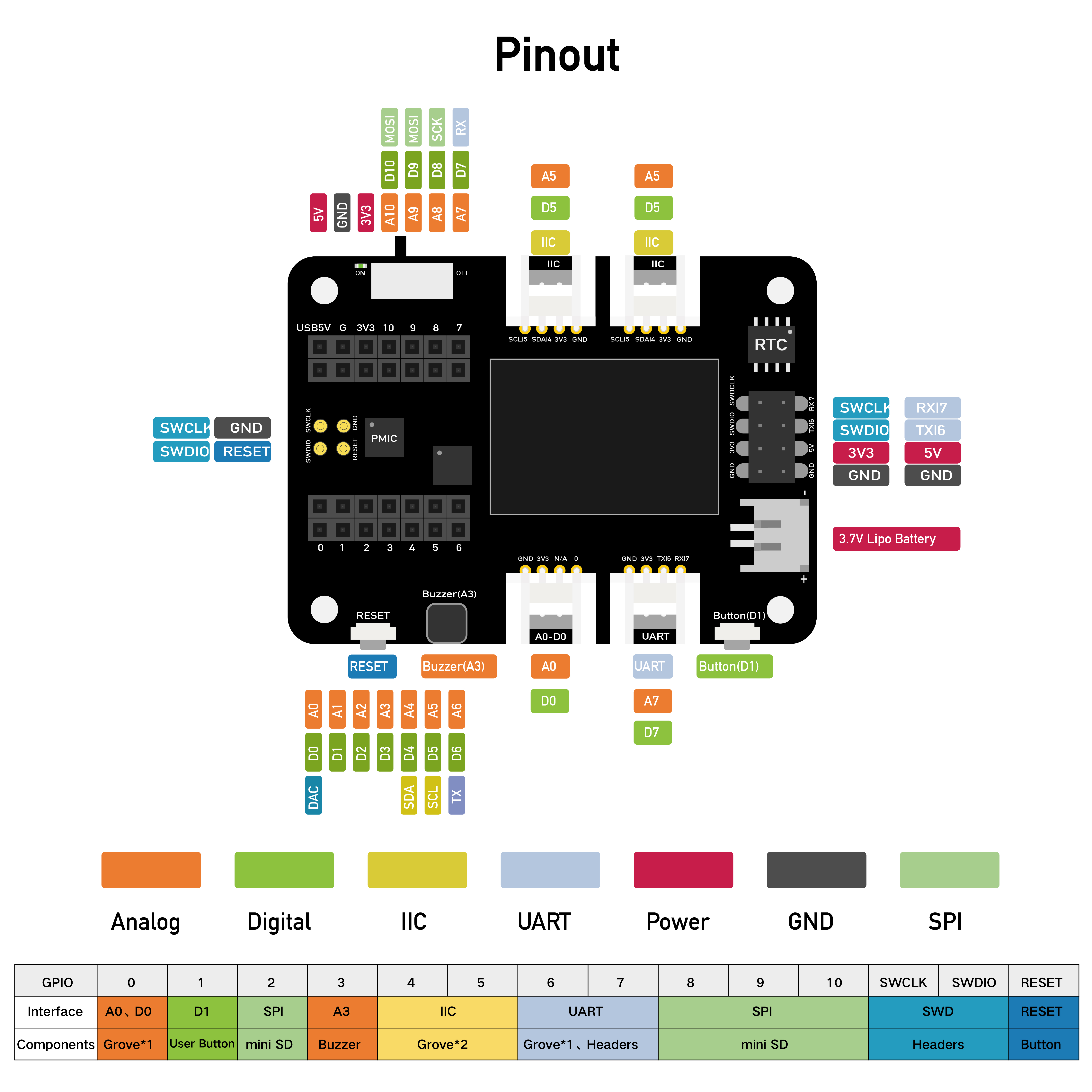
In most cases, the XIAO expansion board is suitable for all Seeed Studio XIAO series products.
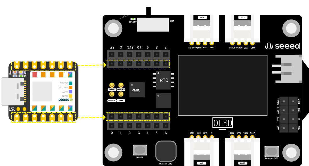
When we need to use the XIAO expansion board, we need to connect the XIAO development board to the corresponding position on the expansion board, as shown in the figure below. Connect the pin headers on the XIAO main board to the position circled in yellow on the expansion board. Be sure to align it before pressing down to avoid damaging the pins. After that, we can start working on projects in combination with the expansion board.
⚠️ Note
Please first plug the Seeed Studio XIAO into the two female headers on the expansion board, and then plug in the Type-C power supply, otherwise it will damage the Seeed Studio XIAO and the expansion board.
1.2.1.2 Three Basic Structures of Programs
The three basic structures of programs are sequential structure, selection structure, and loop structure. 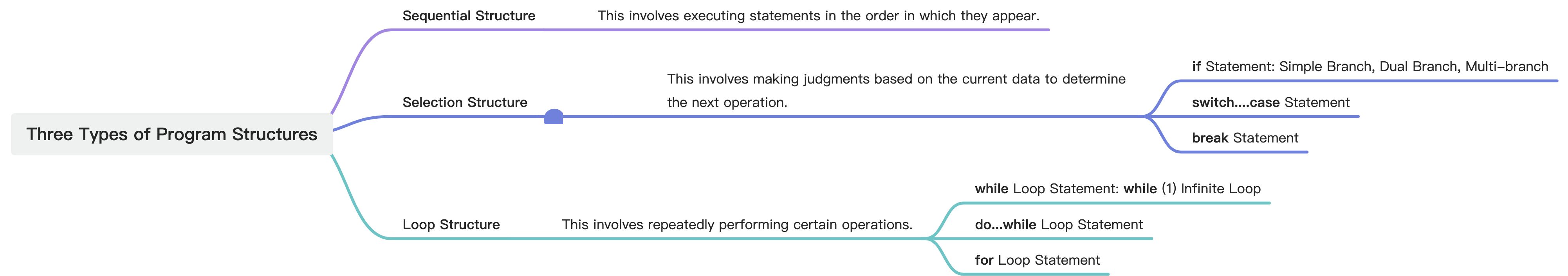
Sequential Structure
As the name suggests, the program in a sequential structure is executed in the order of the statements. It is the most basic and simple program structure. As shown in the figure below, the program will first execute the operation in the S1 box, then the operation in the S2 box, and so on.

Selection Structure
In a program,sometimes we need to make judgments based on the situation to decide the next step. For instance, the program might need to judge the light value in the current environment. If the light value is high, indicating a bright environment, there’s no need to light up the light. If the light value is low, indicating a dim environment, then it’s necessary to turn on the light. In such cases, we use a selection structure.
As shown in the following figures, the selection structure will judge whether the condition is fulfilled. If “True”, it executes S1; if “False”, it executes S2; or if “True”, it executes S1, if “False”, it exits the selection structure.
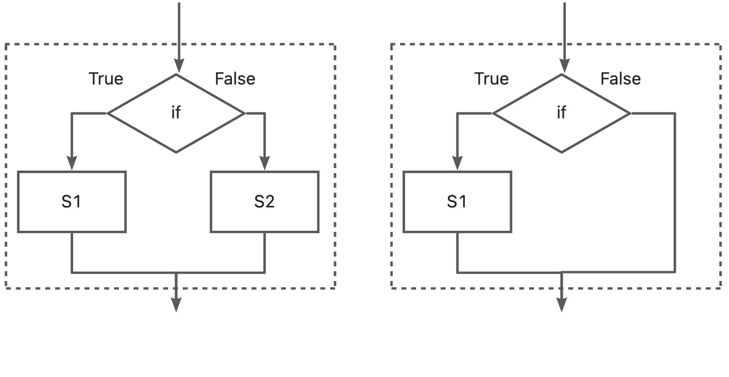
The if Statement
The if statement is the most common selection structure, which executes the following statement when the given expression is true. The if statement has three structural forms as shown in the following example. Simple branch structure: Execute when the condition is fulfilled.
if (expression) {
  statement;
}
Dual branch structure: Execute statement1 when the condition is fulfilled, otherwise execute statement2.
if (expression) {
  statement1;
}
else {
  statement2;
}
Multi-branch structure: Use nested if statements to judge different situations.
if (expression1) {
statement1;
}
else if (expression2) {
statement2;
}
else if (expression3) {
statement3;
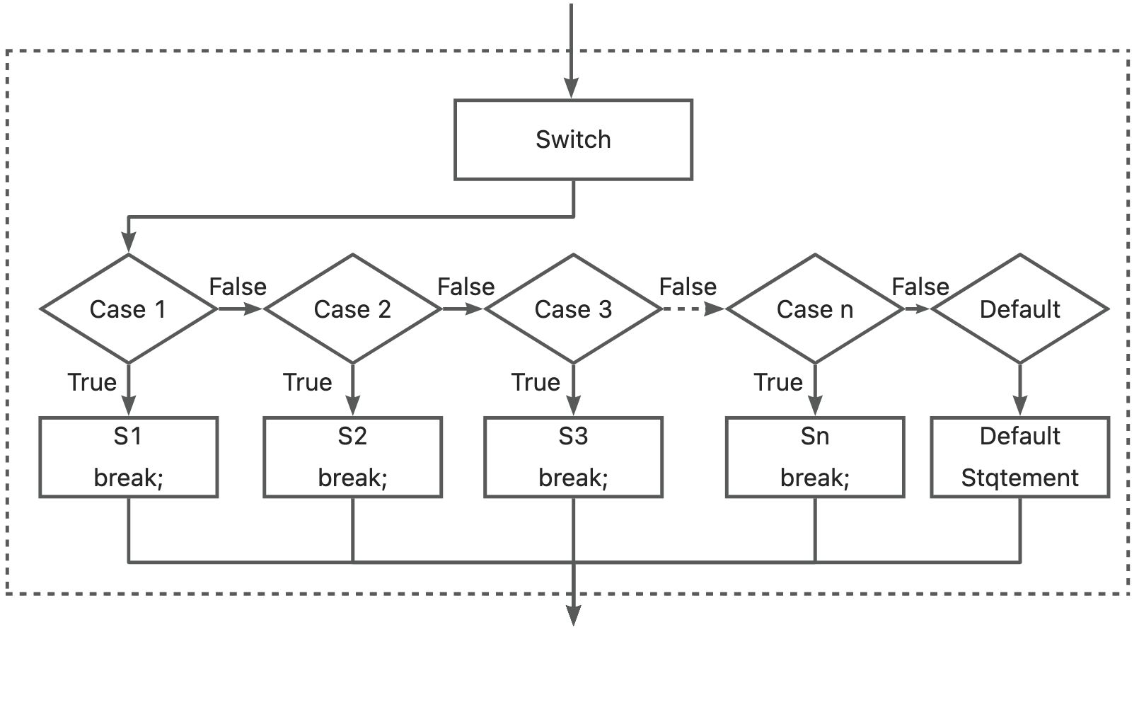
}switch……case Statement
When dealing with multiple selection branches, using an “if……else” structure to write a program can be quite lengthy. In this case, it’s much more convenient to use a switch statement. The switch structure compares the expression in parentheses with the constants after case. If they match, it executes the corresponding statement and exits the structure via a break statement. If none match, it runs the statement after default. It’s important to note that the expression in parentheses after switch must be of integer or character type.
switch (expression) {
  case constant_expression1:
    statement1;
    break;
  case constant_expression2:
    statement2;
    break;
    ……
  default:
    statementn;
    break;
}
break Statement
The break statement can only be used in a switch multi-branch selection structure and loop structures. It is used to terminate the current program structure, allowing the program to jump to subsequent statements for execution.
Loop Structure
A loop structure is used when a part of the program needs to be executed repeatedly, based on given judgment conditions to determine whether to continue executing a certain operation or exit the loop. There are three common types of loop statements:
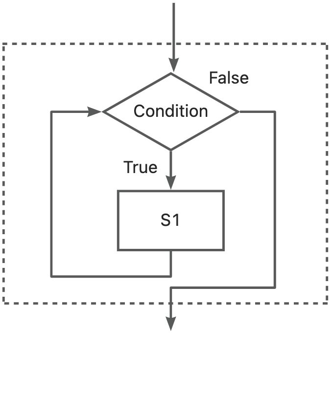
while Loop
The while loop is a type of “when” loop that executes the statements in the loop body when a certain condition is met.
while (expression) {
statement;
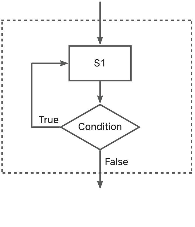
}do……while Loop
This is a type of “until” loop. The statement in the loop body is executed once before the expression is evaluated. If the expression is true, the loop continues.
do {
  statement;
} while (expression);
for Loop
This includes three expressions: Expression1 for initialization, Expression2 for judgment, and Expression3 for increment.
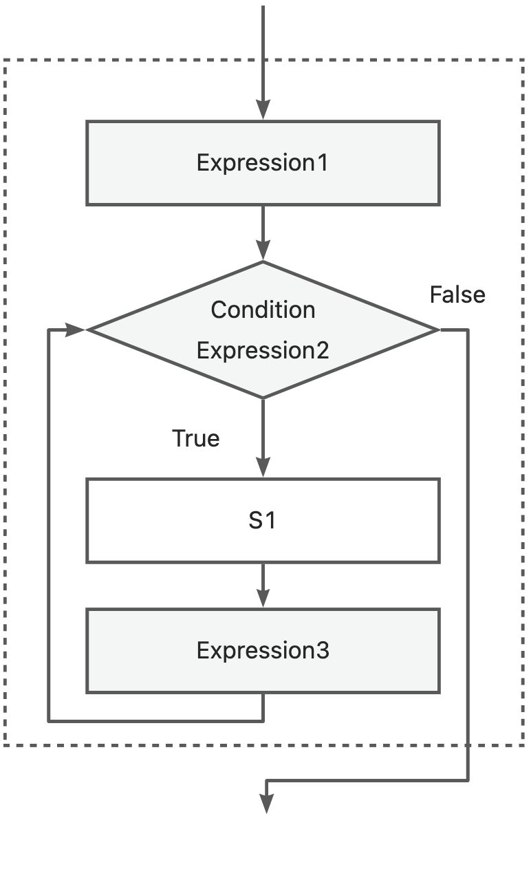
for (Expression1; Expression2; Expression3) {
  statement;
}
In addition to the above loop statements, there are control statements, break and continue, in the loop structure used to prematurely end the loop or exit the loop. In this lesson, we just need to understand these program structures. In later courses, we will gradually master them through project examples.
1.2.2 Task 1: Control the LED on the XIAO using the button on the XIAO expansion board
Analysis
The effect we want to achieve is that when the button is pressed, the LED lights up; when the button is released, the LED goes off. The program is written in three steps:
- Define pins and create variables.
- Initialize and set pin status.
- Read the button status, implement condition judgment. If the button is pressed, the light is on, otherwise, the light is off.
Variable
In a program, a value that can change is called a variable. For example, defining an integer variable
iasint i;. We can assign a value to the variable at the same time as we define it, such asint i =0;. Furthermore, depending on the data type, different statements are used to define variables, such as defining a floating point number,float x = 1.9;, and so on. For more details, refer to the Arduino data types and constants documentation https://www.arduino.cc/reference/en/#variables.
Writing the Program:
Step 1: Define pins and create variables. The on-board button switch on the XIAO expansion board is D1, so we define it as pin 1 and set a variable for the button status. Note that LED_BUILTIN will set the LED to the correct pin, so we don’t need to manually define it:
const int buttonPin = 1;  // The on-board button switch on the XIAO expansion board is D1, which we define as pin 1
// If you are using XIAO RP2040, please change 1 to D1
int buttonState = 0;  // buttonState is a variable to store the button status
Step 2: Set pin status. Set the LED pin to output status and the button pin to input pull-up status. Use INPUT_PULLUP to enable internal pull-up resistors. When the button is not pressed, it returns 1 or HIGH (high level). When the button is pressed, it returns 0 or LOW (low level).
void setup() {
    pinMode(LED_BUILTIN, OUTPUT);// Set the LED pin to output status
    pinMode(buttonPin, INPUT_PULLUP);// Set the button pin to input status
}
Step 3: Continuously read the button status. If the button is pressed, the light is on, otherwise, the light is off. Because the on-board LED of the XIAO is negative logic, when the button is pressed and returns 0, the LED is on; when it returns 1, the LED is off.
void loop() {
    // Read the button status and store it in the buttonState variable
    buttonState = digitalRead(buttonPin);
    // Check whether the button is pressed, if the button is pressed
    if (buttonState == HIGH) {
        // Turn on the LED:
        digitalWrite(LED_BUILTIN, HIGH);
    }
    else {
        // Turn off the LED:
        digitalWrite(LED_BUILTIN, LOW);
    }
}
Get this program from Github
https://github.com/mouseart/XIAO-Mastering-Arduino-and-TinyML/blob/main/code/L2_Button_XIAO_en/L2_Button_XIAO_en.ino
Uploading the Program
We upload the program we wrote to the hardware. First, use the data cable in the kit to connect the XIAO to the computer.
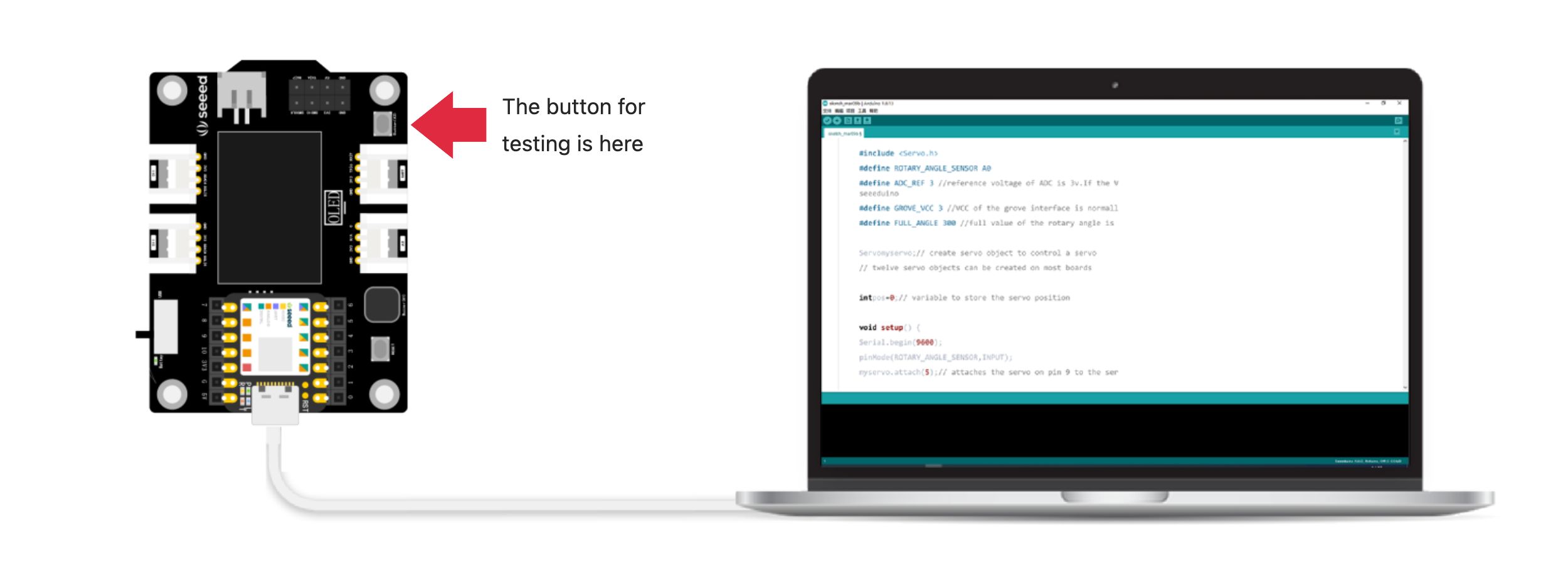
Note the position of the buttons on the XIAO extensions used for testing in the figure.
Then click the verify button ![]() to verify the program. If it is correct, click the upload button
to verify the program. If it is correct, click the upload button ![]() to upload the program to the hardware. When the debugging area displays “Done uploading.”, we can press the button to see if the LED lights up.
to upload the program to the hardware. When the debugging area displays “Done uploading.”, we can press the button to see if the LED lights up.
⚠️ Note
There are two identical buttons on the expansion board. One is the RESET button near the Type-C interface, and the other is the user-defined button near the lithium battery interface. Test with the one near the lithium battery interface.
1.2.3 Task 2: Use the button on the XIAO expansion board to control the external LED on the XIAO ESP32C3
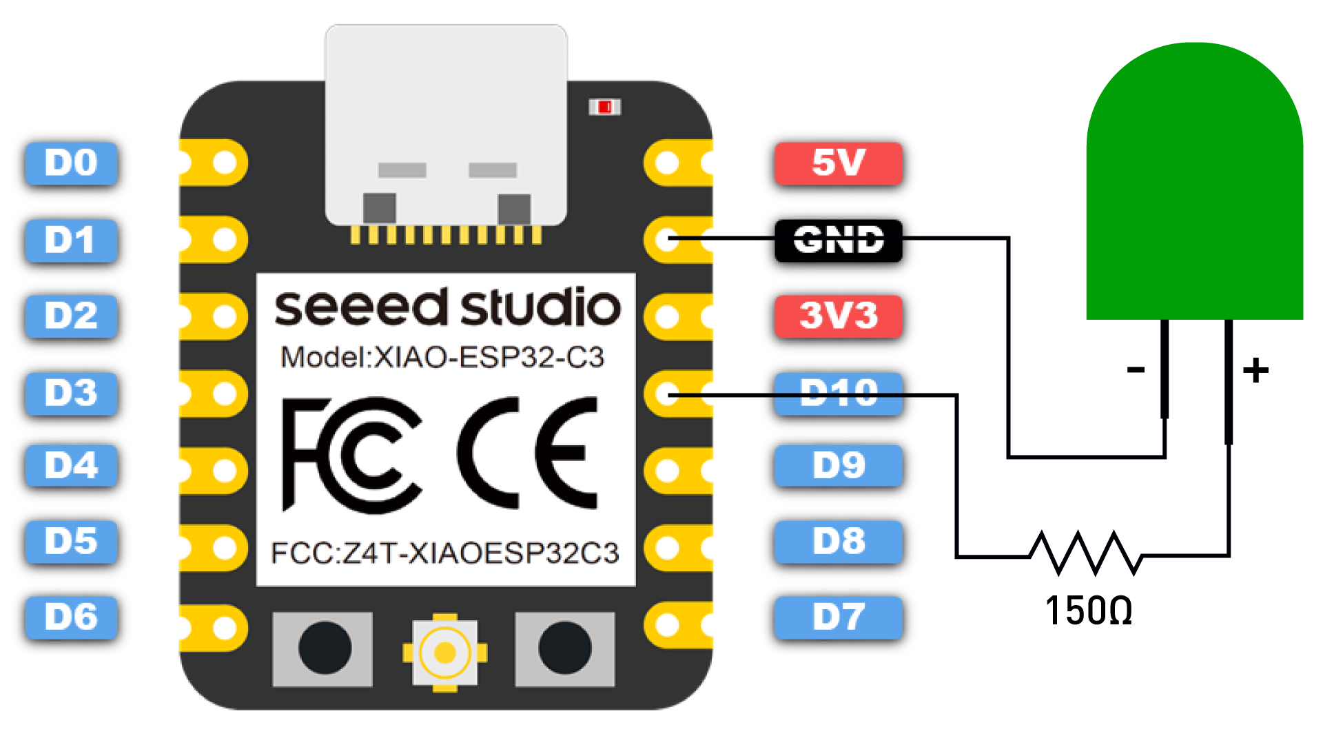
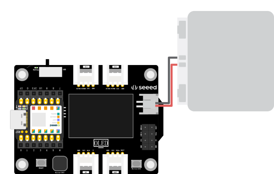
For the Seeed XIAO ESP32C3, it doesn’t have an on-board LED for users to use. To run the Blink program, you need to first connect an LED to the D10 pin of the board as shown:
⚠️ Note
Be sure to add a resistor (about 150Ω) in series with the LED to limit the current flowing through the LED to prevent overcurrent from burning out the LED.
Then copy the following program into the Arduino IDE:
/*
 * Button controlling external LED of XIA

Apologies for the confusion. It seems that there was an issue with quoting text from the document. Let's continue:

#### Task 2: Use the button on the XIAO expansion board to control the external LED on the XIAO ESP32C3
For the Seeed XIAO ESP32C3, it doesn't have an on-board LED for users to use. To execute the Blink program, you first need to connect an LED to the board's `D10` pin as shown.

> ⚠️ Note: Make sure to add a resistor (about 150Ω) in series with the LED to limit the current flowing through the LED and prevent overcurrent from burning out the LED.

Then, copy the following program into the Arduino IDE:
```cpp
/*
 * Button controlling external LED of XIAO ESP32C3
 */

const int buttonPin = 1;     // The pin number of the button
int buttonState = 0;    // Variable for reading the button status
int led = D10;  // Pin number of the LED

void setup() {
  // Initialize the LED pin as an output:
  pinMode(led, OUTPUT);
  // Initialize the button pin as an input:
  pinMode(buttonPin, INPUT_PULLUP);
}

void loop() {
  // Read the state of the button:
  buttonState = digitalRead(buttonPin);
  // Check if the button is pressed. If it is, the button state is HIGH
  if (buttonState == HIGH) {
    // Turn the LED on:
    digitalWrite(led, HIGH);
  }
  else {
    // Turn the LED off:
    digitalWrite(led, LOW);
  }
}
Get this program from Github
https://github.com/mouseart/XIAO-Mastering-Arduino-and-TinyML/tree/main/code/L2_Button_XIAO_ESP32C3_en
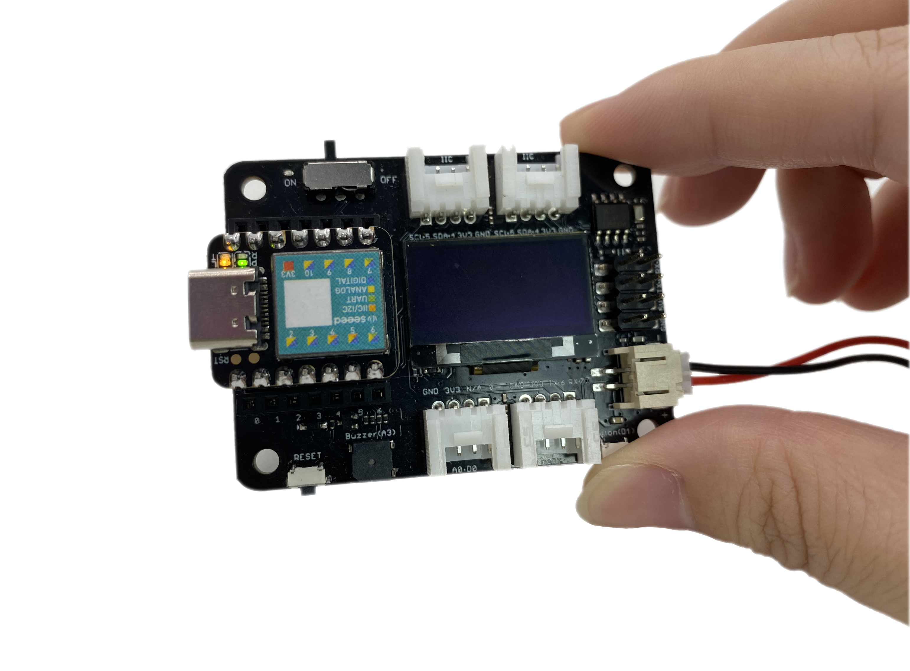
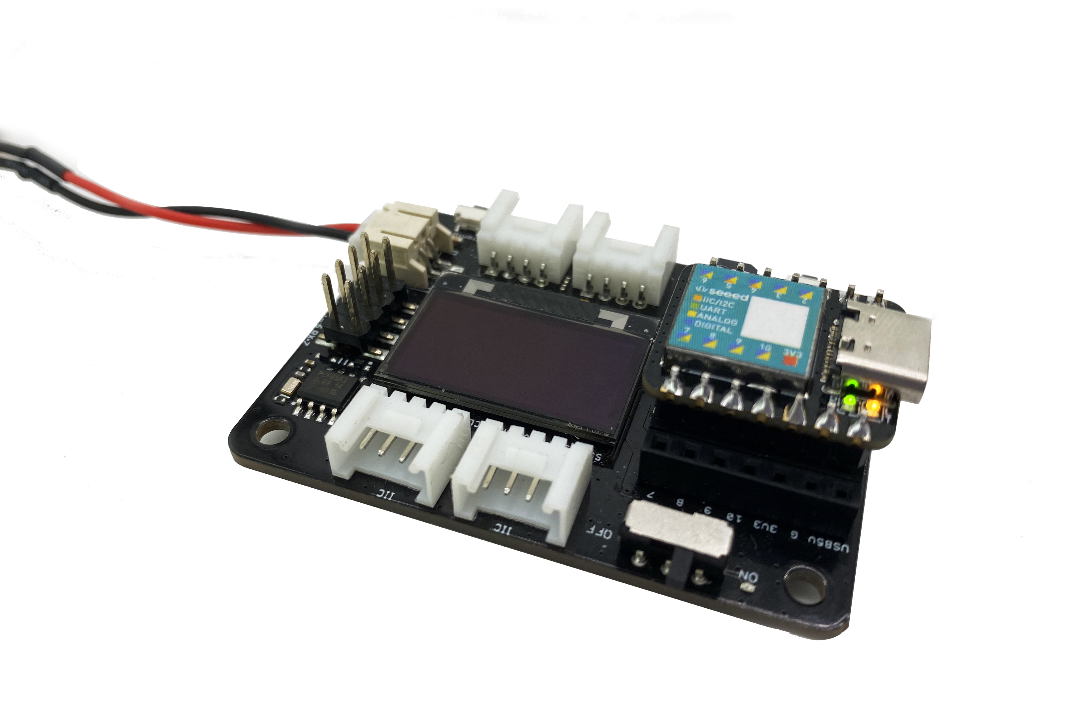
Powering XIAO with an external battery
When demonstrating the effect, in addition to using a data cable to power the computer, you can also use an external lithium battery. This makes it convenient to move and do projects, as shown in the picture.
1.2.4 Expanded Exercise
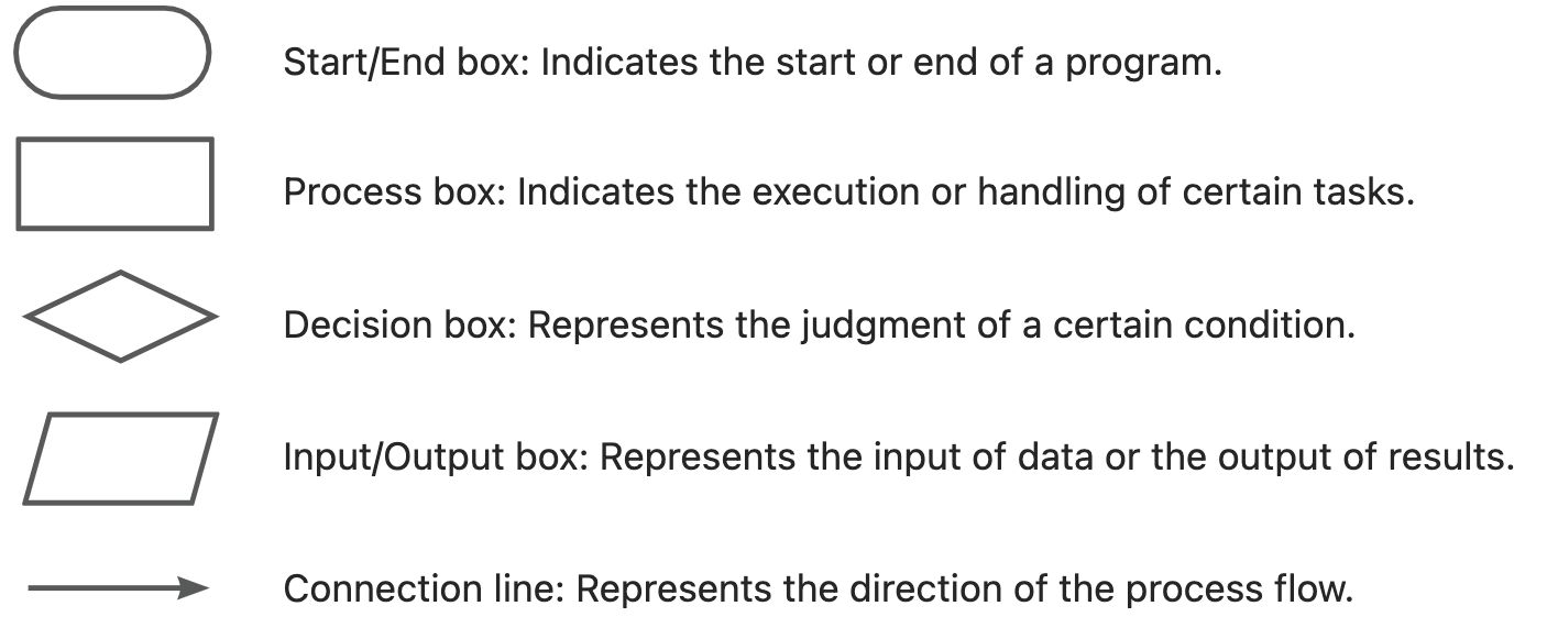
Flow Chart
Before writing the program, you can first draw a flow chart of the program to help organize your thoughts. The common flow chart symbols are as follows:
The button-controlled LED program we implemented in this section is represented by the following flow chart. You can try drawing it yourself.
