1.3 Transforming XIAO and its Expansion Board into a Morse Code Transmitter
Everyone knows that “SOS” is an internationally recognized emergency signal, a form of Morse code. Today, we will transform Seeed Studio’s XIAO into a Morse code transmitter. We will try to make the onboard buzzer of the expansion board send signals automatically. In addition, we will learn how to control the buzzer manually with a button.
1.3.1 Background Knowledge
1.3.1.1 Buzzer
A buzzer is an integrated electronic sound device that generates sound based on the input of an electrical signal. Buzzers are often installed on electronic products for sound generation. There are two types of buzzers: active (source buzzers) and passive (sourceless buzzers).
- Active Buzzers: These buzzers have a simple oscillation circuit inside. When connected to a DC power supply, the buzzer can convert a constant DC into a certain frequency pulse signal, thereby driving the internal aluminum sheet to vibrate and make a sound. Active buzzers can usually only emit some fixed-pitch (frequency) sounds and are widely used in the sound devices of computers, printers, copiers, alarms, electronic toys, car electronics, phones, timers, and other electronic products.
- Passive Buzzers: These buzzers work similarly to loudspeakers. They don’t have an internal oscillator and need to be connected to a changing current signal to work. They usually use different frequency square wave signals for driving. The sound generated by passive buzzers will change according to the change in input signal, and they can output a variety of sounds like speakers, not just emitting a fixed single tone (frequency).

The standalone buzzer module is shown in the figure below.
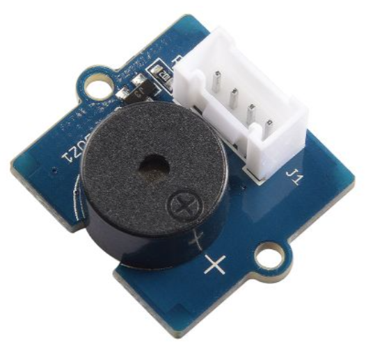
In the Seeed Studio XIAO expansion board, there is an onboard passive buzzer connected to pin A3. We can output PWM pulse signals to this pin to control the buzzer.

1.3.1.2 tone() and noTone() Functions
tone()Function
The tone()function can generate a fixed frequency PWM signal to drive a passive buzzer to make a sound, and it can define the frequency and duration of the sound.
Syntax:
tone(pin, frequency);
tone(pin, frequency, duration);
Parameters:
pin: The pin to which the buzzer is connected (in the Seeed Studio XIAO expansion board, it’s A3).
frequency:The frequency of the sound (unit: Hz), the type allowed is unsigned integer.
duration:The duration of the sound (unit: milliseconds, this parameter is optional), the type allowed is unsigned long.
noTone() Function
This function is used to stop the sound of the buzzer controlled by the tone() function. If there is no sound generated, the function is invalid.
Syntax:
noTone(pin);
Parameters:
pin: The pin to stop the sound.
1.3.1.3 Common Operators
In previous studies, we have used some operators. Next, we will learn about common types of operators and their usage methods.
Arithmetic Operators:
| Operator | Explanation |
|---|---|
| = | Assignment operator |
| + | Addition operator |
| - | Subtraction operator |
| * | Multiplication operator |
| / | Division operator |
| % | Modulus operator |
Comparison Operators:
| Operator | Explanation |
|---|---|
| != | Not equal to |
| < | Less than |
| <= | Less than or equal to |
| == | Equal to |
| > | Greater than |
| >= | Greater than or equal to |
Boolean Operators:
| Operator | Explanation |
|---|---|
| && | Logical “and” |
| ! | Logical “not” |
Compound Operators:
| Operator | Explanation |
|---|---|
| ++ | Self-increment |
| += | Compound addition |
| – | Self-decrement |
| -= | Compound subtraction |
For detailed explanations, see: https://www.arduino.cc/reference/en/
1.3.1.4 Morse Code
Morse code is a method of expressing information in telecommunication, named after the inventor of the telegraph, Samuel Morse.

Source of the picture: https://en.wikipedia.org/wiki/Samuel_Morse
The international Morse code encodes the 26 English letters A to Z, some non-English letters, Arabic numbers, and a small number of punctuation marks and prosigns. There is no distinction between upper and lower case letters. Each Morse code symbol consists of a series of dots (·) and dashes (—). The duration of a dot is the basic unit of time measurement in Morse code transmission. The duration of a dash is three times the duration of a dot. After each dot or dash in a character, there is a time when the signal is absent, called a space, equal to the duration of a dot. For example, the standard emergency distress signal SOS is expressed in Morse code as shown in the figure below.

If it’s expressed in sound, it sounds like this.
1.3.2 Task 1: Automatic Broadcasting of “SOS”
Analysis
Automatic broadcasting means that when the control board is started, the onboard buzzer automatically emits the Morse code of “SOS”. The program is written in three steps:
- Define the buzzer pin
- Initialization, setting the state of the buzzer pin
- Loop the buzzer to play the Morse code of “SOS”
Let’s first look at how to reflect the Morse code of “SOS” through the program. If you import the audio file of Morse code into the audio editing software, you can see the waveform of the sound and the duration of each syllable, which is generally divided into long and short sounds. To facilitate understanding and programming, we use a binary way to mark the switch of the buzzer, 1 indicates the buzzer is on, 0 indicates the buzzer is off, and the gray number represents how long the current status needs to last. After a Morse code ends, because it needs to be looped, you need to leave time between the two Morse codes, here it is set to 0.8 seconds.

To emit a short sound, which corresponds to a dot in Morse code, from the buzzer, you can use the following code in Arduino:
tone(pinBuzzer, 200);
delay(100);
noTone(pinBuzzer);
delay(100);
In this code snippet:
tone(pinBuzzer, 200)generates a sound at a frequency of 200 Hz on the buzzer connected to thepinBuzzerpin.delay(100)waits for 100 milliseconds. This is how long the sound lasts.noTone(pinBuzzer)stops the sound on the buzzer.- The final
delay(100)ensures there’s a pause before the next sound is generated, representing the space between the signals.
The code you provided is a complete Arduino program for emitting the SOS Morse code signal using a buzzer. Here is the English explanation:
Writing the Program
Step 1: Define pins and create variables
int pinBuzzer = 3; // Define the buzzer on pin 3, if you're using XIAO RP2040/XIAO ESP32, change 3 to A3Step 2: Set pin state
void setup() {
    pinMode(pinBuzzer, OUTPUT); // Set the buzzer pin to output state
}
Step 3: Loop to play “SOS” Morse code
void loop() {
    // Emit three short signals:
    for(int i = 0; i < 3; i++){
        tone(pinBuzzer, 200);
        delay(100);
        noTone(pinBuzzer);
        delay(100);
    }
    delay(200);

    // Emit three long signals:
    for(int i = 0; i < 3; i++){
        tone(pinBuzzer, 200);
        delay(300);
        noTone(pinBuzzer);
        delay(100);
    }
    delay(200);

    // Emit three short signals again:
    for(int i = 0; i < 3; i++){
        tone(pinBuzzer, 200);
        delay(100);
        noTone(pinBuzzer);
        delay(100);
    }
    delay(800); // Wait before repeating
}
Get this program from Github
https://github.com/mouseart/XIAO-Mastering-Arduino-and-TinyML/tree/main/code/L3_SOS_XIAO_en
Uploading the Program
To upload the program to your hardware, connect your XIAO to your computer using the data cable included in the kit. After this, click on the verify button ![]() to check your program. If it passes verification, click on the upload button
to check your program. If it passes verification, click on the upload button ![]() to upload the program to your hardware. When the debug area shows “Done uploading.”, you can listen to the Morse code sound. Is it the rhythm you expected?
to upload the program to your hardware. When the debug area shows “Done uploading.”, you can listen to the Morse code sound. Is it the rhythm you expected?
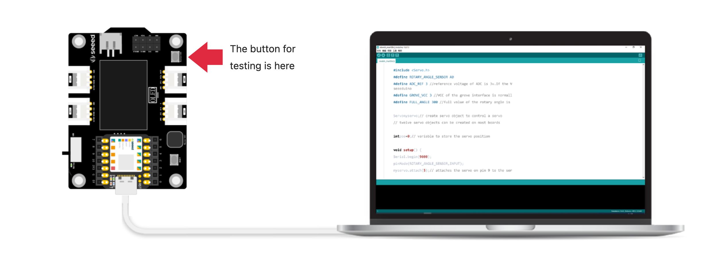
Note the position of the buttons on the XIAO extensions used for testing in the figure.
1.3.3 Task 2: Control the buzzer with a button
Controlling the buzzer with a button to emit Morse code can be done manually. The code logic is simple: use an if statement to determine if the button is pressed. If it is, then the buzzer emits a sound.
Analysis
The program is also written in three steps:
- Define the buzzer and button pins.
- Initialize by setting the state of the buzzer and button pins.
- Determine whether the button is pressed; if pressed, emit a sound.
Write the program:
Step 1: Define the buzzer and button pins
const int buttonPin = 1; // The button is on pin 1, if you are using XIAO RP2040/XIAO ESP32, please change 1 to D1
int pinBuzzer = 3;// The buzzer is on pin 3, if you are using XIAO RP2040/XIAO ESP32, please change 3 to A3
Step 2: Set the button and buzzer pin states
void setup() {
    // Set the buzzer pin as output:
    pinMode(pinBuzzer, OUTPUT);
    // Set the button pin as input:
    pinMode(buttonPin, INPUT_PULLUP);
}
Step 3: Check the button state, if the button is pressed, the buzzer sounds. Here, the tone() function is used to control the passive buzzer to make a sound.
void loop() {
    // buttonState is the button variable, read the button state and store it in the variable:
    int buttonState = digitalRead(buttonPin);

    // Check if the button is pressed, if the button is pressed:
    if (buttonState == LOW) {
        // The buzzer sounds with a frequency of 200, for a duration of 200 milliseconds
        tone(pinBuzzer, 200, 200);
    }
}
⚠️ Note:
There are two identical buttons on the expansion board, one is the RESET button, which is closer to the Type-C interface, and the other is the user-defined button, which is closer to the lithium battery interface. When testing, press the one closer to the lithium battery interface.
The complete program is as follows:
/*
 * Button-SOS
 */
const int buttonPin = 1; // The button is on pin 1, if you are using XIAO RP2040/XIAO ESP32, please change 1 to D1!
int pinBuzzer = 3; // The buzzer is on pin 3, if you are using XIAO RP2040/XIAO ESP32, please change 3 to A3!
void setup() {
  // Set the buzzer pin as output:
  pinMode(pinBuzzer, OUTPUT);
  // Set the button pin as input:
  pinMode(buttonPin, INPUT_PULLUP);
}

void loop() {
  // buttonState is the button variable, read the button state and store it in the variable:
  int buttonState = digitalRead(buttonPin);

  // Check if the button is pressed, if the button is pressed:
  if (buttonState == LOW) {
    // The buzzer sounds with a frequency of 200, for a duration of 200 milliseconds
    tone(pinBuzzer, 200, 200);
  }
}
Get this program from Github
https://github.com/mouseart/XIAO-Mastering-Arduino-and-TinyML/tree/main/code/L3_ButtonSOS_XIAO_en
Uploading the program
We will upload the written program to the hardware. First, connect the XIAO to your computer using the data cable from the kit.

Next, click the ![]() (verify button) to validate the program. If there are no errors, click the
(verify button) to validate the program. If there are no errors, click the ![]() (upload button) to upload the program to the hardware. When the debug area shows “Done uploading.”, we can press the button on the XIAO expansion board and test whether the buzzer will sound.
(upload button) to upload the program to the hardware. When the debug area shows “Done uploading.”, we can press the button on the XIAO expansion board and test whether the buzzer will sound.
1.3.4 Extended Exercise
The passive buzzer can emit different pitches to form a simple melody. Research how to make Arduino play notes through a search engine. You can open the extended exercise code to experience the effect of playing “Happy Birthday” with the buzzer.
Get this program from Github
https://github.com/mouseart/XIAO-Mastering-Arduino-and-TinyML/tree/main/code/L3_HappyBirthday_en