2.2 Smart Hygrometer and Thermometer
Thermometers and hygrometers are ubiquitous in daily life, providing real-time measurement of temperature and humidity in our environment. We frequently use them to measure body temperature when we feel feverish or unwell. The invention of these devices has brought tremendous convenience to our lives. Despite their size, these devices hold a great deal of science. In this section, we will create a smart hygrometer and thermometer using a temperature and humidity sensor. Do you know what a temperature and humidity sensor is and what it can do?
2.2.1 Background Knowledge
2.2.1.1 Temperature
Temperature is closely tied to our daily lives; it informs what clothes we wear before stepping out, and ensures the food or drink we consume is not too hot or too cold. When you step outside your home, you can sense the cold or heat, but to quantify exactly how cold or hot it is, we use “temperature”.
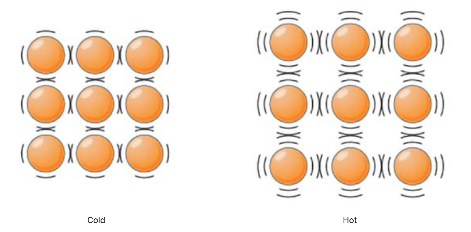
Temperature is a physical quantity that indicates the degree of coldness or hotness of an object. The high and low temperature of an object is a macroscopic phenomenon that reflects the intensity of thermal motion of the molecules that make up the object at the microscopic level. Hence, the temperature is a manifestation of the intensity of thermal motion of a large number of molecules that constitute an object. The faster the molecular motion, the higher the temperature, and the hotter the object; the slower the molecular motion, the lower the temperature, and the colder the object.
To measure temperature accurately, we need to establish a temperature unit standard and design corresponding temperature measurement tools.
Temperature Scale
The unit standard for temperature is known as the temperature scale. Throughout the development of science, a variety of temperature scales have been devised, but their core methodology is the same: by stipulating the temperature values of certain phenomena or things, all other temperatures can be calibrated. Common temperature scales include Fahrenheit, Celsius, and Kelvin. Only five countries, including the United States and a few other English-speaking countries, still use the Fahrenheit scale. The vast majority of the world, including China, uses the Celsius scale. In research fields, scientists prefer to use the Kelvin scale.
- In the Fahrenheit scale, under standard atmospheric pressure, the temperature at which water begins to freeze is set at 32 degrees Fahrenheit and the temperature at which water boils is 212 degrees Fahrenheit. The scale is divided into 180 equal parts between these two points, with each part being one degree Fahrenheit, denoted as 1℉. In the Fahrenheit scale, normal human body temperature is around 98℉.
- In the Celsius scale, under standard atmospheric pressure, the temperature at which water begins to freeze is set at 0 degrees Celsius and the temperature at which water boils is 100 degrees Celsius. The scale is divided into 100 equal parts between these two points, with each part being one degree Celsius, denoted as 1℃. In the Celsius scale, normal human body temperature is around 36.5℃.
- The Kelvin scale is established on the basis of absolute zero. Scientists found that there is a minimum temperature in the universe, -273.15℃, which cannot be reached but only asymptotically approached. This minimum temperature was designated as absolute zero, and set as 0 Kelvin, denoted as 0K. The temperature at which water begins to freeze under standard atmospheric pressure is set at 273.15K, and the temperature at which water boils is 373.15K. In the Kelvin scale, normal human body temperature is around 309.7K.
2.2.1.2 Thermometer
A thermometer is a tool for measuring temperature. Since temperature is not a physical quantity that can be seen directly, the measurement of temperature requires the assistance of physical phenomena directly related to temperature. For instance, in ancient China, there is a record of ‘lustrous pure blue flame,’ which is measured by observing the color of the flame.
Another example is the infrared thermometer, as shown in the image to the right, which measures temperature through the radiation differences of objects at different temperatures. Humans, like other organisms, also radiate infrared energy around them. This energy typically has a wavelength of 9-13μm and falls within the near-infrared band of 0.76-100μm. Since light within this wavelength range is not absorbed by air, the surface temperature of the human body can be accurately measured by simply measuring the infrared energy radiated by the human body. The human body infrared temperature sensor is designed and manufactured based on this principle.

Furthermore, the phenomenon of thermal expansion and contraction is often used in temperature measurement. Commonly seen thermometers and body thermometers are based on the principle of measuring temperature by the expansion and contraction of a liquid when heated or cooled. The image below shows a commonly used alcohol thermometer that measures temperature by the property of alcohol’s expansion and contraction with temperature. The winter daytime temperature displayed in the image is -17°C.

2.2.1.3 Humidity
Humidity is a physical quantity that indicates the degree of dryness in the atmosphere. Under a certain temperature, the less water vapor a certain volume of air contains, the drier the air; the more water vapor, the more humid the air. The dryness or wetness of air is called “humidity.” Weather forecasts typically report humidity values in terms of relative humidity, which is a percentage obtained by comparing the actual amount of water vapor in the air to the maximum amount of water vapor the air can hold at the same temperature.

2.2.1.4 Temperature and Humidity Sensor —— Grove Temperature and Humidity Sensor V2.0 (DHT20)
As the name implies, a temperature and humidity sensor is a sensor that can detect the temperature and humidity in the environment. There are many types of temperature and humidity sensors, and the one we chose is Grove Temperature and Humidity Sensor V2.0 (DHT20). This is a low-power, high-precision, and high-stability product with a fully calibrated digital I2C interface and a temperature measurement range of -40~80°C. Temperature and humidity sensors have a wide range of applications in the fields of agriculture, environmental protection, and home life.

⚠️ Grove - Temperature and Humidity Sensor (DHT11)
If you are using the Grove DHT11 version of the temperature and humidity sensor (with a blue sensor case), please refer to this version’s Wiki document. DHT11 is a temperature and humidity sensor that outputs calibrated digital signals. The biggest difference between it and DHT20 is their communication method: DHT11 uses a single-bus digital signal, while DHT20 uses an I2C signal.

2.2.2 Task 1: Reading Temperature and Humidity Values in the Serial Monitor (Based on the DHT20 model)
Adding the Grove_Temperature_And_Humidity_Sensor Library File
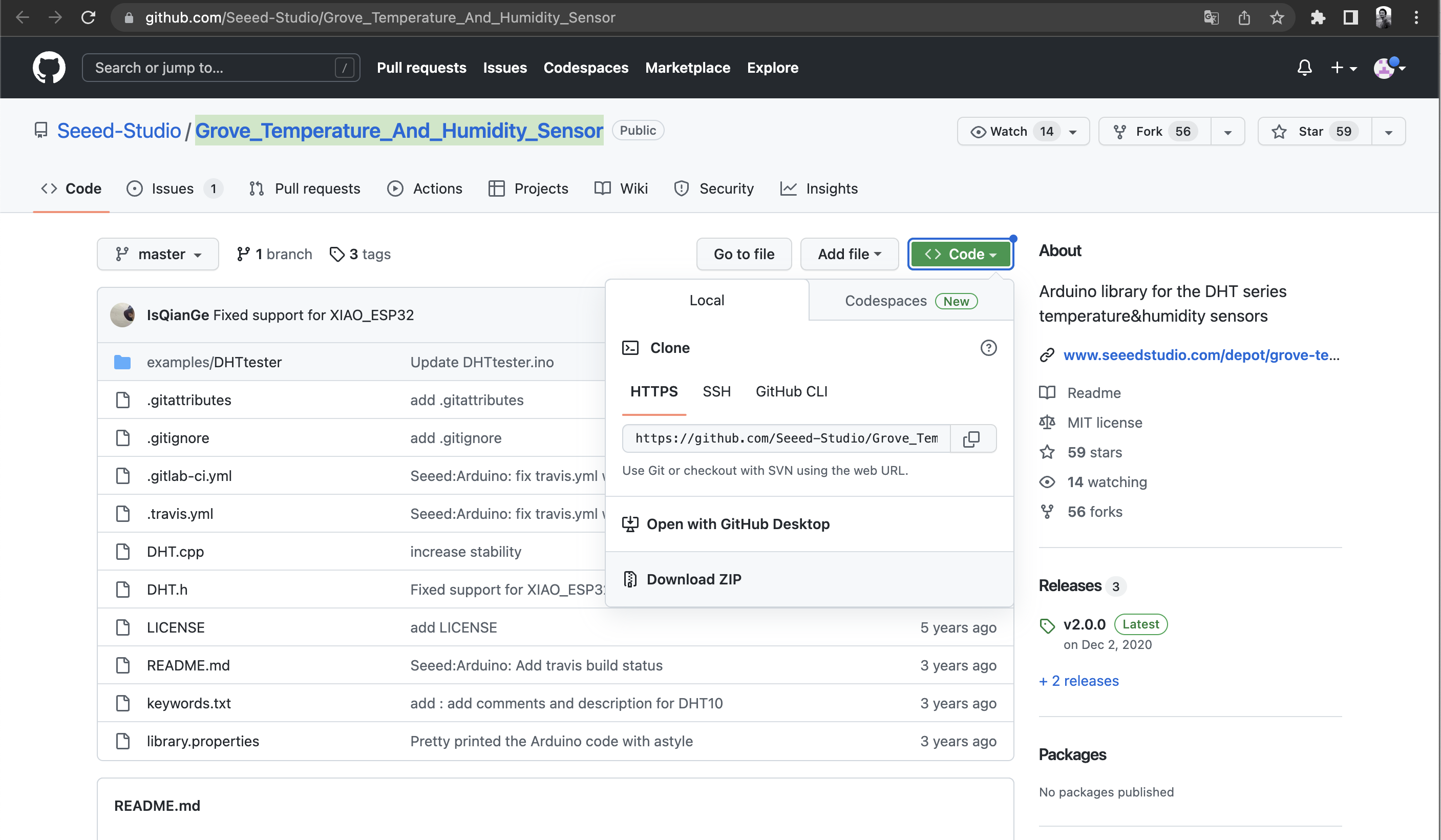
Before starting to program the Grove Temperature and Humidity Sensor with the Arduino IDE, it is necessary to add the necessary library files for the sensor. Type the library file address in the browser address bar: 🔗 https://github.com/Seeed-Studio/Grove_Temperature_And_Humidity_Sensor, enter the GitHub page, and click Code→Download ZIP to download the resource package Grove_Temperature_And_Humidity_Sensor-master.zip to your local machine, as shown in the image below.
Add the resource package Grove_Temperature_And_Humidity_Sensor-master.zip downloaded in the previous step in the menu bar’s Sketch→Include Library→Add .ZIP Library, until you see a prompt indicating the successful loading of the library.
Opening the “DHTtester” Example
Once the library file has been successfully added, the DHT library can be used. The “DHTtester” example can be opened through the following path: File→Examples→Grove Temperature And Humidity Sensor→DHTtester.
⚠️ Note If the DHTtester example is not found in the menu after installing the library files, it can be viewed by closing and reopening the Arduino IDE.
After opening the example program, we can see a program like the one shown below. This program reads the temperature and relative humidity in the environment and displays real-time data in the serial monitor. Part of the example program’s code needs to be modified.
// Example testing sketch for various DHT humidity/temperature sensors
// Written by ladyada, public domain

#include "DHT.h"

// Uncomment whatever type you're using!
//#define DHTTYPE DHT11   // DHT 11
#define DHTTYPE DHT22   // DHT 22  (AM2302)
//#define DHTTYPE DHT21   // DHT 21 (AM2301)
//#define DHTTYPE DHT10   // DHT 10
//#define DHTTYPE DHT20   // DHT 20

/*Notice: The DHT10 and DHT20 is different from other DHT* sensor ,it uses i2c interface rather than one wire*/
/*So it doesn't require a pin.*/
#define DHTPIN 2     // what pin we're connected to(DHT10 and DHT20 don't need define it)
DHT dht(DHTPIN, DHTTYPE);   //   DHT11 DHT21 DHT22
//DHT dht(DHTTYPE);         //   DHT10 DHT20 don't need to define Pin

// Connect pin 1 (on the left) of the sensor to +5V
// Connect pin 2 of the sensor to whatever your DHTPIN is
// Connect pin 4 (on the right) of the sensor to GROUND
// Connect a 10K resistor from pin 2 (data) to pin 1 (power) of the sensor


#if defined(ARDUINO_ARCH_AVR)
    #define debug  Serial

#elif defined(ARDUINO_ARCH_SAMD) ||  defined(ARDUINO_ARCH_SAM)
    #define debug  SerialUSB
#else
    #define debug  Serial
#endif

void setup() {

    debug.begin(115200);
    debug.println("DHTxx test!");
    Wire.begin();

    /*if using WIO link,must pull up the power pin.*/
    // pinMode(PIN_GROVE_POWER, OUTPUT);
    // digitalWrite(PIN_GROVE_POWER, 1);

    dht.begin();
}

void loop() {
    float temp_hum_val[2] = {0};
    // Reading temperature or humidity takes about 250 milliseconds!
    // Sensor readings may also be up to 2 seconds 'old' (its a very slow sensor)


    if (!dht.readTempAndHumidity(temp_hum_val)) {
        debug.print("Humidity: ");
        debug.print(temp_hum_val[0]);
        debug.print(" %\t");
        debug.print("Temperature: ");
        debug.print(temp_hum_val[1]);
        debug.println(" *C");
    } else {
        debug.println("Failed to get temprature and humidity value.");
    }

    delay(1500);
}
Pay attention to the document’s comments. The program above provides several types of temperature and humidity sensor models (DHT22 is set as default), but we need the DHT20. So, uncomment the part for DHT20 and delete the definitions for other unneeded sensor models. DHT10 and DHT20 do not require pin definitions, so the revised code after modification is as follows:
#include "DHT.h"
#define DHTTYPE DHT20   // DHT 20
DHT dht(DHTTYPE);
#if defined(ARDUINO_ARCH_AVR)
#define debug  Serial

#elif defined(ARDUINO_ARCH_SAMD) ||  defined(ARDUINO_ARCH_SAM)
#define debug  Serial
#else
#define debug  Serial
#endif

void setup() {
    debug.begin(115200);
    debug.println("DHTxx test!");
    Wire.begin();
    dht.begin();
}

void loop() {
    float temp_hum_val[2] = {0};
    if (!dht.readTempAndHumidity(temp_hum_val)) {
        debug.print("Humidity: ");
        debug.print(temp_hum_val[0]);
        debug.print(" %\t");
        debug.print("Temperature: ");
        debug.print(temp_hum_val[1]);
        debug.println(" *C");
    } else {
        debug.println("Failed to get temprature and humidity value.");
    }

    delay(1500);
}
Get this program from Github https://github.com/mouseart/XIAO-Mastering-Arduino-and-TinyML/tree/main/code/L8_DHTtester_DHT20_XIAO_en
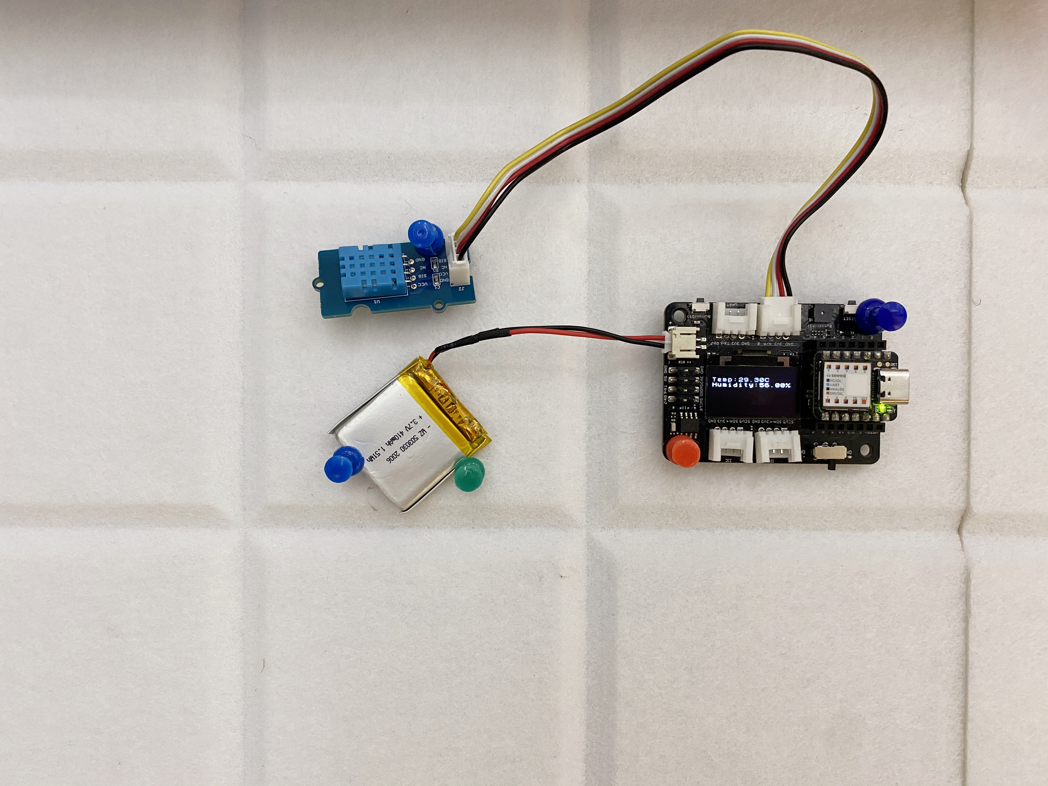
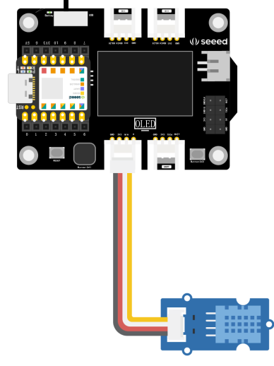
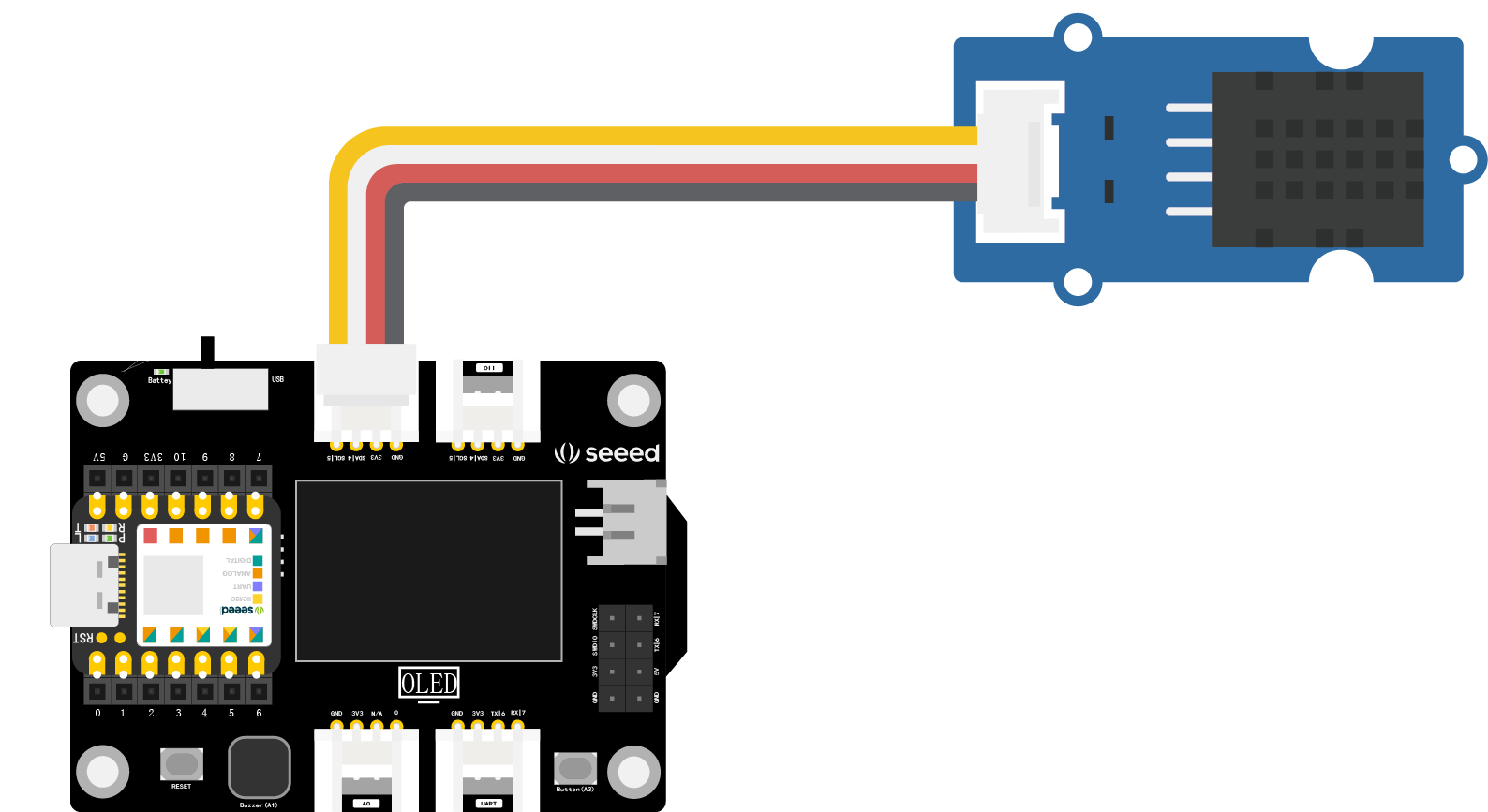
After modifying the code, first connect the temperature and humidity sensor to the I2C interface of the XIAO expansion board, as shown below. Then connect the XIAO development board to your computer, upload the modified example program to XIAO in the Arduino IDE, and open the serial monitor in Arduino IDE. You will now be able to see the values of temperature and humidity. Try placing the sensor in different environments to observe if the temperature and humidity values change.

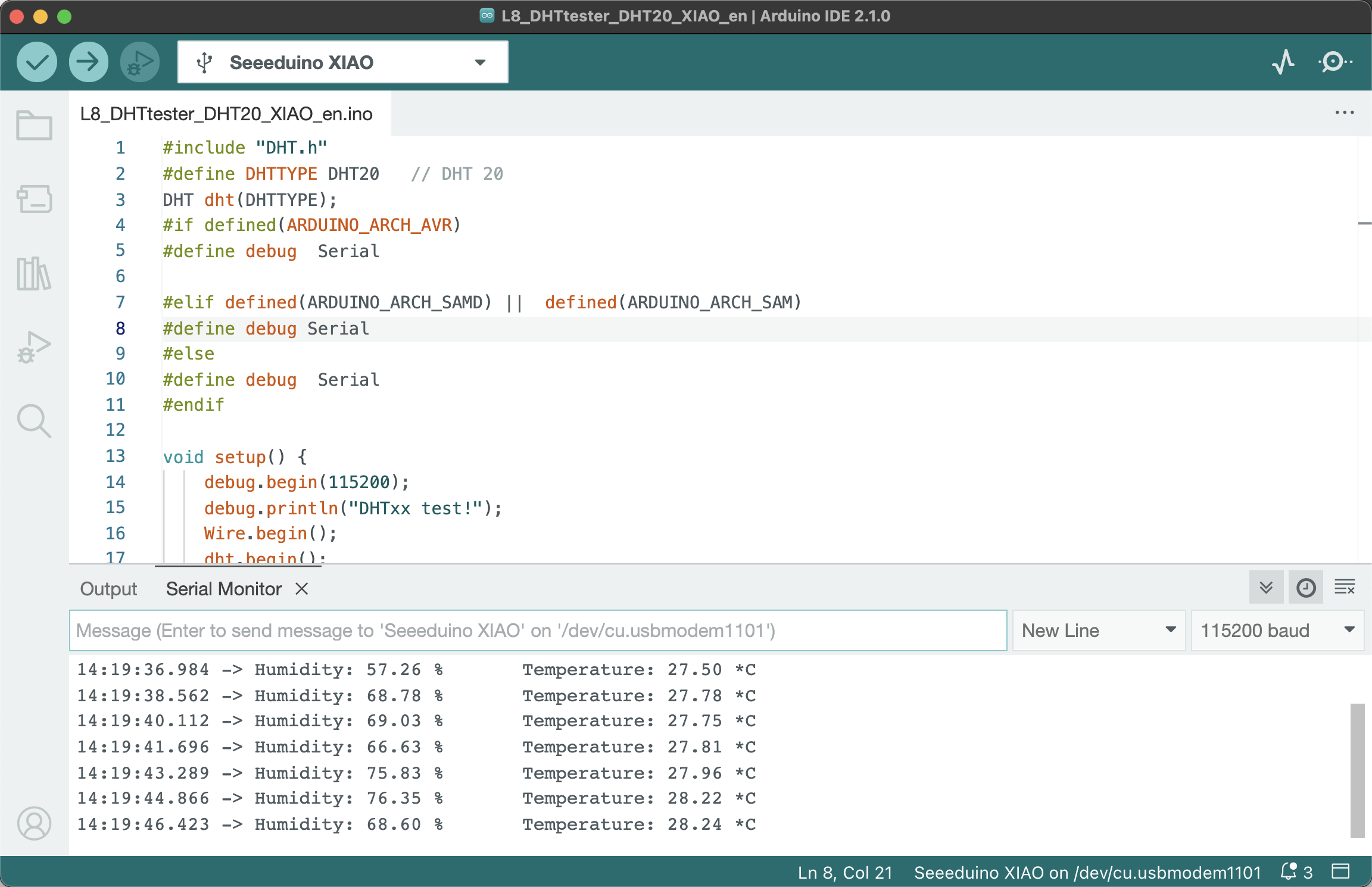
It appears the temperature and humidity sensor is functioning correctly.
Reading Temperature and Humidity Values in the Serial Monitor (Based on the DHT11 Sensor)
If you are using the Grove DHT11 Temperature and Humidity Sensor with a blue casing, parts of the program code need to be modified as follows:
#define DHTPIN 0 needs to be modified according to the actual pin number the sensor is connected to.
#define DHTTYPE DHT11 should be set because there are different models of temperature and humidity sensors, and you need to choose the correct one, i.e., DHT11.
The example code after modification is shown below:
#include "DHT.h"
#define DHTTYPE DHT11   // DHT 11
#define DHTPIN 0
DHT dht(DHTPIN, DHTTYPE);

#if defined(ARDUINO_ARCH_AVR)
    #define debug  Serial

#elif defined(ARDUINO_ARCH_SAMD) ||  defined(ARDUINO_ARCH_SAM)
    #define debug  SerialUSB
#else
    #define debug  Serial
#endif

void setup() {
    debug.begin(115200);
    debug.println("DHTxx test!");
    Wire.begin();
    dht.begin();
}

void loop() {
    float temp_hum_val[2] = {0};
    if (!dht.readTempAndHumidity(temp_hum_val)) {
        debug.print("Humidity: ");
        debug.print(temp_hum_val[0]);
        debug.print(" %\t");
        debug.print("Temperature: ");
        debug.print(temp_hum_val[1]);
        debug.println(" *C");
    } else {
        debug.println("Failed to get temprature and humidity value.");
    }

    delay(1500);
}
Get this program from Github
https://github.com/mouseart/XIAO-Mastering-Arduino-and-TinyML/tree/main/code/L8_DHTtrster_DHT11_XIAO_en
After modifying the code, first connect the temperature and humidity sensor to the A0 port of the XIAO expansion board, as shown in the figure below. Then, connect the XIAO development board to the computer, upload the modified example program to XIAO in the Arduino IDE, and open the serial monitor in the Arduino IDE to see the values of temperature and humidity. You can place the temperature and humidity sensor in different environments to see if the temperature and humidity values will change.
2.2.3 Project Creation: Smart Temperature and Humidity Meter
Project Description
We are going to make a portable mini temperature and humidity detector that detects temperature and humidity values through a temperature and humidity sensor and displays the values on the OLED display of the XIAO expansion board. However, it is not rich enough to have only the display function. We can add a buzzer alarm function. When the detected temperature and humidity exceed a certain range, an alarm will be sounded as a reminder. The value range can be adjusted according to different application scenarios. For example, in a home life scenario, set a comfortable temperature and humidity range based on human feelings; or use it in plant planting places, set the temperature and humidity value range based on suitable plant growth, exceed the alarm, and remind people to adjust.
Program Writing
Referencing the example program above, one of the effects we want to achieve is to display the temperature and humidity values on the OLED display of the XIAO expansion board. The code for reading the temperature and humidity sensor detection values can be reused by just changing the display medium. In combination with Section 1.6, we have learned how to display characters on the OLED, so we just need to add an if…else condition judgment statement to judge the temperature and humidity values. The program writing idea is as follows:
- Declare the DHT.h library, U8x8 library, etc., and connect the buzzer pin as a reminder to sound the device.
- Initialize the library file, define the buzzer pin state.
- Define temperature and humidity variables to store readings and display them on the OLED screen, add logical judgment, and implement buzzer alarm.
To facilitate understanding and implementation, we divide the program implementation into two tasks:
- Detect temperature and humidity and display them on the OLED screen of the XIAO expansion board.
- Add alarm function.
Task 1: Use the Grove DHT20 sensor to detect temperature and humidity and display them on the OLED screen of the XIAO expansion board
Step 1: Headers, declare the library files to be called.
#include "DHT.h"    //Use DHT library
#include <Arduino.h>
#include <U8x8lib.h>    //Use u8x8 library
#define DHTTYPE DHT20
DHT dht(DHTTYPE);   //DHT20 does not need to define pins

U8X8_SSD1306_128X64_NONAME_HW_I2C u8x8(/* reset=*/ U8X8_PIN_NONE);  //Setup constructor to connect to OLED screen
Step 2: Initialize the DHT library and the u8x8 library.
void setup() {
    Wire.begin();   //Initialize wire library, and join I2C network
    dht.begin();    //DHT starts working
    u8x8.begin();   //u8x8 starts working
    u8x8.setPowerSave(0);  //Turn off power saving mode, 1 is on, and nothing can be seen on the screen after power saving mode is on
    u8x8.setFlipMode(1);
}
Step 3: Define temperature and humidity variables to store readings, read temperature and humidity values and display them on the OLED screen. Pay attention to the coordinate positions of temperature and humidity display.
void loop() {
    float temp, humi;   //Set the variables temp and humi to floating point type, representing temperature and humidity respectively
    temp = dht.readTemperature();   //Read temperature value and store it in temp
    humi = dht.readHumidity();  //Read humidity value and store it in humi
    u8x8.setFont(u8x8_font_chroma48medium8_r);  //Set display font
    u8x8.setCursor(0, 33);  //Set the position of the drawing cursor (0,33)
    u8x8.print("Temp:");    //Display Temp at the position (0,33)
    u8x8.print(temp);   //Display real-time temperature value
    u8x8.print("C");    //Display the unit "C" of temperature
    u8x8.setCursor(0,50);
    u8x8.print("Humidity:");
    u8x8.print(humi);
    u8x8.print("%");
    u8x8.refreshDisplay();
    delay(200);
}
Get this program from Github https://github.com/mouseart/XIAO-Mastering-Arduino-and-TinyML/tree/main/code/L8_dht20_tem_humi_XIAO_en
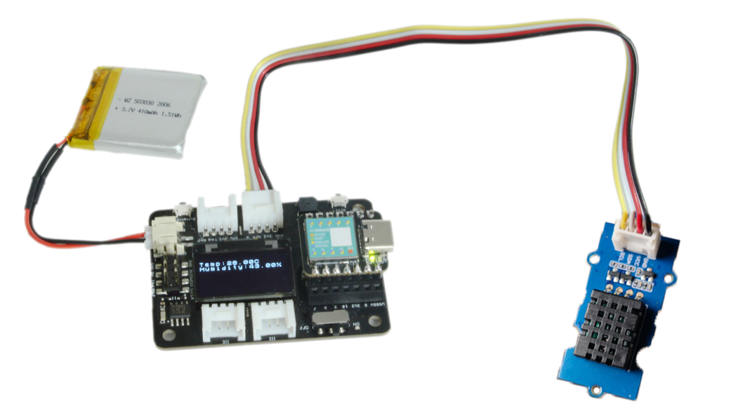
Step 4: Connect the hardware, upload the program Connect the temperature and humidity sensor to the I2C interface of the XIAO expansion board, as shown in the figure:
Use the data cable to connect XIAO to the computer, click the “upload” button in the Arduino IDE, and upload the program to the hardware. When the debugging area shows “upload successful”, you can observe whether the temperature and humidity values are displayed on the OLED screen, and you can hold the black part of the sensor with your palm to observe whether the values change.
Task 2: Add an alarm function
Step 1: Add alarm function code. The alarm function requires a buzzer to be integrated into the circuit, which can be facilitated using the on-board buzzer of the XIAO expansion board. The program needs to set the buzzer pin state, add a part for condition judgment - when the temperature exceeds a certain value or the humidity falls below a certain value, the buzzer will sound an alarm. Here, a logical expression needs to be written using the “&&” logical operator “and”.
Boolean Operators
&&: Logical AND, represents “and”,if (expression1 && expression2), only when all expressions in the parentheses aretruewill it execute the statements inif {}.||: Logical OR, represents “or”,if (expression1 || expression2), if either of the expressions are satisfied, the entire expression istrue, and the statements inif {}are executed.!: Logical NOT, represents “not”,if (!expression1), only when the value of expression1 in the parentheses isfalsewill it execute the statements inif {}.Usage example:
When the temperature exceeds 30 or the humidity falls below 40, satisfying either condition will make the buzzer sound an alarm.
if (temp > 30 || humi < 40) {
    tone(buzzerPin, 200, 200);
}
The added part of the program mainly sets the buzzer and makes decisions based on temperature and humidity, controlling the buzzer to make a sound.
// Part of the program, will not run
int buzzerPin = A3; // Connects the buzzer to pin A3

void setup() {
    pinMode(buzzerPin , OUTPUT); // Sets the buzzer pin as output
}

void loop() {
    float temp, humi;
    temp = dht.readTemperature();
    humi = dht.readHumidity();
    if (temp > 30 || humi < 40) {  // When the temperature exceeds 30 or the humidity falls below 40, satisfying either condition will make the buzzer sound an alarm.
        tone(buzzerPin, 200, 200);
    }
Add the above code to the corresponding location of the Task 1 program to realize all functions. The complete program is shown below:
#include "DHT.h" // Use DHT library
#include <Arduino.h>
#include <U8x8lib.h> // Use u8x8 library
#define DHTTYPE DHT20
DHT dht(DHTTYPE); // DHT20 does not require pin definition
int buzzerPin = A3;
U8X8_SSD1306_128X64_NONAME_HW_I2C u8x8(/* reset=*/ U8X8_PIN_NONE); // Set constructor to connect OLED display

void setup() {
    pinMode(buzzerPin , OUTPUT); // Set buzzer pin to output mode
    Wire.begin(); // Initialize Wire library and join to I2C network
    dht.begin(); // DHT begins operation
    u8x8.begin(); // u8x8 begins operation
    u8x8.setPowerSave(0);  // Disable power save mode, 1 is enable. After enabling power save mode, nothing will be seen on the screen
    u8x8.setFlipMode(1);
}

void loop() {
    float temp, humi; // Set variables temp and humi to floating point type, representing temperature and humidity respectively
    temp = dht.readTemperature(); // Read temperature value and store it in temp
    humi = dht.readHumidity(); // Read humidity value and store it in humi
    if (temp > 30 || humi < 40) {  // When the temperature is above 30 or the humidity is below 40, if either condition is met, the buzzer will sound an alarm
        tone(buzzerPin, 200, 200);
    }

    u8x8.setFont(u8x8_font_chroma48medium8_r); // Set display font
    u8x8.setCursor(0, 33); // Set the position of the drawing cursor (0,33)
    u8x8.print("Temp:"); // Display "Temp:" at the position (0,33)
    u8x8.print(temp); // Then display the real-time temperature value
    u8x8.print("C"); // Then display the unit of temperature "C"
    u8x8.setCursor(0,50);
    u8x8.print("Humidity:");
    u8x8.print(humi);
    u8x8.print("%");
    u8x8.refreshDisplay();
    delay(200);
}
Get this program from Github
https://github.com/mouseart/XIAO-Mastering-Arduino-and-TinyML/tree/main/code/L8_dht20_alarm_XIAO_en
Step 2: Upload the program.
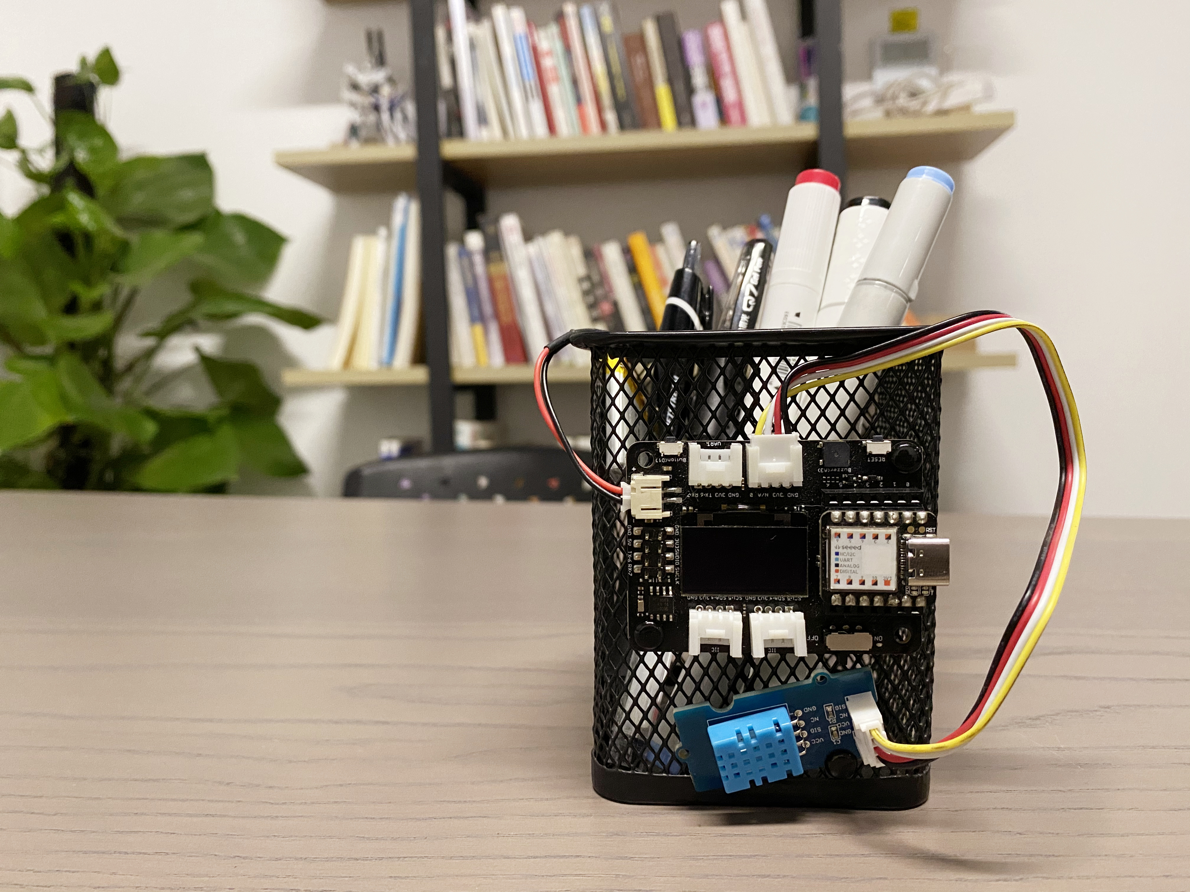
After writing the program, connect the XIAO main control board to the computer using a data cable, as shown in the image below:
After connection, click the “Verify” button to check the program. If the verification is successful, click the “Upload” button to upload the program to the hardware. When the debugging area shows “Upload Successful”, it is complete. To verify whether the alarm function runs smoothly, tightly grip the temperature and humidity sensor with your hand, observe the value change on the OLED display, and listen for the buzzer alarm when the temperature exceeds 30℃.
Task 2-2: Use Grove DHT11 sensor to display temperature and humidity on the XIAO extension board’s OLED and add an alarm function.
For the Grove DHT11 sensor with a blue casing, the program is shown below:
#include "DHT.h"//Use DHT library
#include <Arduino.h>
#include <U8x8lib.h>//Use u8x8 library
#define DHTPIN 0
#define DHTTYPE DHT11//Specify using DHT11
DHT dht(DHTPIN, DHTTYPE);
int buzzerPin = A3;
U8X8_SSD1306_128X64_NONAME_HW_I2C u8x8(/* reset=*/ U8X8_PIN_NONE);//Set constructor to connect OLED display

void setup() {
  pinMode(buzzerPin , OUTPUT);//Set buzzer pin to output mode
  Wire.begin();//Initialize wire library and join to I2C network
  dht.begin();//DHT begins operation
  u8x8.begin();//u8x8 begins operation
  u8x8.setPowerSave(0);  //Disable power save mode, 1 is enable. After enabling power save mode, nothing will be seen on the screen
  u8x8.setFlipMode(1);
}

void loop() {
  float temp, humi;//Set variables temp and humi to floating point type, representing temperature and humidity respectively
  temp = dht.readTemperature();//Read temperature value and store it in temp
  humi = dht.readHumidity();//Read humidity value and store it in humi
  if (temp > 30 || humi < 40) {  //When the temperature is above 30 or the humidity is below 40, if either condition is met, the buzzer will sound an alarm
  tone(buzzerPin, 200, 200);
  }

  u8x8.setFont(u8x8_font_chroma48medium8_r);//Set display font
  u8x8.setCursor(0, 33);//Set the position of the drawing cursor (0,33)
  u8x8.print("Temp:");//Display "Temp:" at the position (0,33)
  u8x8.print(temp);//Then display the real-time temperature value
  u8x8.print("C");//Then display the unit of temperature "C"
  u8x8.setCursor(0,50);
  u8x8.print("Humidity:");
  u8x8.print(humi);
  u8x8.print("%");
  u8x8.refreshDisplay();
  delay(200);
}
Get this program from Github https://github.com/mouseart/XIAO-Mastering-Arduino-and-TinyML/tree/main/code/L8_dht11_alarm_XIAO_en
2.2.4 Appearance Design
Starting from this section, we will add the part of appearance design, beginning to explore the complete prototype product manufacturing. Initially, we can try to draw design sketches and make a simple modification with the materials at hand. Returning to the smart temperature and humidity meter in this section, please design the appearance of the prototype work based on the product characteristics and functions.
| Product Name | Smart Temperature and Humidity Meter |
|---|---|
| Product Features | Small, portable, high sensitivity. |
| Product Functions | Real-time display of temperature and humidity values, and emits an alarm when temperature and humidity values exceed the comfortable range. |
| Product Appearance | (For example, made into a pendant to hang on the backpack that is carried around, stick on the tissue storage box in the bedroom, etc.) |
Case reference