2.1 Introduction to Product Prototype Design
In the first unit, we’ve entered the realm of electronic hardware and programming, learning how to control electronic hardware through code to achieve desired effects, such as controlling an LED in various ways, making a buzzer sound, displaying text on an OLED screen, and more. Mastering this knowledge will help us turn the ideas in our minds into reality. In this section, we will learn about the process from an idea to a prototype and then to a product. Only when you have mastered this knowledge can you step into the world of product prototype design. If you have managed to stick with this course up to this point, there’s no doubt that you are a “maker” at heart. The idea of “wanting to make something on your own” keeps swirling around in your mind. This section will provide you with some advice on how to become a maker and guidance on how to create electronic product prototype designs.
2.1.1 Cultivating the Maker Mindset
Becoming an excellent maker is not just about learning hardware modules and programming knowledge, but also consciously cultivating some habits.

Dale Dougherty, the founder of Make: magazine, gave some advice on cultivating the maker mindset in his welcome speech at Maker Camp (refer to 🔗 https://makercamp.com/get-started).
Keep it playful
Play opens us to creative ideas and new experiences. While we play, we engage our bodies and our mind, and we often engage with others. While we play, learning feels natural and we can take risks to do things we didn’t know we can do.
Be Curious
Ask questions – who, what, why, and how. How are things around you made? Who makes them and where are they made?
Get physical
Use your sense to experience the physical world all around you. What are the differences between the natural world and the built world?
Find a favorite tool
Tools exist for all kinds of applications. Given an area you’re interested such as bicycles or music, what are some of the tools, both physical and digital, that you might want to learn to use? Choose a new tool and share it with us.
Do something you’ve never done before
Sometimes we decide that we’re not good at something and we never try to do it. Part of the DIY spirit is to try something you’ve never tried before, even if you’re not particularly good at it. Think of it as an experiment. See if you like it. Try cooking or gardening or playing a musical instrument. Or try to fix something that’s broken. Share this new skill.
Make something
You might design something that solves a problem — it could be a problem for you or a problem for others. You might build something that’s interactive such as a play toy, or a toy car or plane. Paper airplane launchers are popular, as are rockets.
What are the benefits of engaging young people in making?
Here are the five key competencies that we identified as outcomes for young people who participate in Start Making!
- Identify as a creator or maker. Young people develop positive attitudes toward creating hands-on projects.
- Develop confidence in creative expression. Young people feel capable of bringing their ideas to life by designing, experimenting, iterating, and persisting through failures.
- Acquire technical tool literacy. Young people become familiar with a variety of tools and technologies that they can use to make projects.
- Become aware of STEAM. Young people become aware of ideas and concepts that bridge science, technology, engineering, art, and math and demonstrate curiosity to learn more.
- Learn collaboration and networking skills. Young people actively engage in collaborating and helping others.
Start Making! A Guide to Engaging Young People in Maker Activities By Danielle Martin and Alisha Panjwani edited by Natalie Rusk
What are the attributes of a maker? What is a maker mindset?
- Makers are curious. They are explorers. They pursue projects that they personally find interesting.
- Makers are playful. They often work on projects that show a sense of whimsy.
- Makers are willing to take on risk. They aren’t afraid to try things that haven’t been done before.
- Makers take on responsibility. They enjoy taking on projects that can help others.
- Makers are persistent. They don’t give up easily.
- Makers are resourceful. They look for materials and inspiration in unlikely places.
- Makers share—their knowledge, their tools, and their support.
- Makers are optimistic. They believe that they can make a difference in the world.
Making Makers: Kids, Tools and the Future of Innovation By AnnMarie Thomas
2.1.2 Enlightening on Product Prototype Design
Author Introduction:
Wen Yanming, a post-90s female, graduated from the Chinese University of Hong Kong and South China University of Technology, with a master’s degree in law. She is a hardware product manager, an inventor, an entrepreneur, with over a decade of technology practice and maker experience.

2.1.2.1 Basic Process of Product Prototype Design
From idea to product prototype and then to the product, this is a process that every product must go through. A product prototype allows us to quickly verify ideas, functionality, and product feasibility in a cost-effective way, providing the basis for product testing, optimization, and iterative updates. Behind every successful product we see, there may have been countless iterations of product prototypes. Therefore, creating a good product prototype is an essential process and solid foundation for a successful product.
The prototypes needed for different types of products and different stages of the product are not the same. When we mention a product prototype, it may refer to a conceptual prototype, a functional prototype, a small batch production prototype, a factory hand model, etc. It should be noted that for electronic hardware products, the discussion here is mainly about product prototypes for product concepts and functional implementation.
Generally speaking, the design of a functional product prototype mainly includes the following processes:
1. Identify and Clarify the Problem to be Solved
Einstein once said: “Posing a problem is often more important than solving a problem.” Every product must exist to solve a certain problem or to provide some benefit to people. Therefore, identifying and clarifying the problem to be solved is a prerequisite for clarifying product design needs and proceeding with product design.
It is important to note that just because we have identified a problem does not mean we truly understand and accurately define this problem. For example, over 100 years ago, when Henry Ford, the founder of Ford Motor Company, went around asking customers what kind of transportation they needed, almost everyone’s answer was, “I want a faster horse.” But do people really just need a faster horse? If Mr. Ford had defined the problem based on this, we might not have had faster and more comfortable cars so quickly.

2. Demand Analysis and Product Definition
Once the problem is clearly defined, we can extract unmet needs from it. Like the example above, the problem at that time was actually how to get to the destination faster, so the corresponding need was “a faster mode of transportation,” not “a faster horse.” Therefore, we need to be good at digging deeper from the problems we discover to find the real needs. Demand analysis generally requires an analysis of the user population and use scenarios, from which to derive the functions needed to solve the problem, that is, to clarify: for whom, in what scenarios, to achieve what functions, to gain what benefits.

There are many types of needs: true user needs, superficial needs, urgent needs, ordinary needs, high-frequency needs, low-frequency needs, and so on. All of these need to be analyzed in light of the actual situation, which can then inform the correct definition of the product based on these needs.
Every product ultimately needs to be commercialized to realize its maximum value. Therefore, when designing a product for the market, we also need to conduct a series of market analyses, including market size, sales expectations, profit analysis, payback period, input-output ratio analysis, and so on.
3. Hardware Selection and Assembly
For the design of electronic products, once the needs are defined, we need to find hardware that can implement these functional needs. When choosing hardware, the elements that generally need to be considered include: feasibility, level of need satisfaction, cost, volume, weight, performance, lifespan, appearance, etc. One of the most important abilities of an excellent product designer is to take into account various factors based on the product definition and needs, balance these factors, and make trade-offs. Often, there is no single correct answer.
Generally speaking, when we build a prototype, the first thing we should consider is creating a minimum viable product (MVP). Its function is to use the least resources to quickly verify the product and quickly improve and iterate.

4. Software Development and Functional Implementation
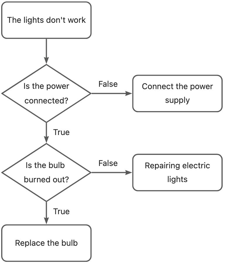
Many experienced software development engineers will draw a functional implementation flowchart before software development. They will draw a functional implementation flowchart according to the functions to be implemented. This can help clarify the software design thinking, check the function logic, facilitate the identification of leaks and deficiencies, and refer to it at any time during programming, ensuring they have a clear understanding. Therefore, regardless of the complexity of software function development, it is recommended that everyone develop a good habit of drawing a functional implementation flowchart first. It can be a simple hand-drawn sketch, or a professional software like Visio, Axure can be used to draw it.
When developing software, try to be efficient and concise. Take full advantage of the benefits of the open-source community and learn to use existing hardware and software resources more effectively. For example, many pieces of hardware or applications already have many ready-made open-source libraries and routines. During development, you can refer to these, comply with the corresponding open-source agreements to use related resources, and avoid wasting time reinventing the wheel.
5. Prototype Testing and Optimization
After the prototype is made, we need to test it to verify its functional implementation and whether it meets the original design needs. This process should involve as many target users as possible to collect their feedback. In this way, we can better discover the defects in the product prototype, make remedial measures and improvements, update and iterate the design, and finally make a design scheme that meets user needs, laying a solid foundation for formal product design.
2.1.2.2 Product Prototype Practice - “One Meter Distance Alarm” Prototype

Next, let’s take the prototype manufacturing process of the “One Meter Distance Alarm” as an example to experience the product prototype design process.
1. Identifying and Defining the Problem to be Solved
At the beginning of 2020, the COVID-19 pandemic broke out globally, the situation was very severe. To prevent the virus from spreading through droplets and close-range airborne contact, governments and health departments around the world urged everyone to reduce gatherings and maintain social distancing of at least one meter whenever possible. However, it is not easy for everyone to constantly remember this and maintain an accurate social distance of more than one meter. For children, they often forget to maintain distance because they are playing happily, or they have no concept of how far they should keep their distance. When going out, there are also some strangers who, due to a lack of epidemic prevention awareness, unconsciously come close to us, and we need to find a polite way to remind them.
Therefore, we have derived a question from life: How can we constantly remind people to maintain a social distance of more than one meter?
2. Needs Analysis and Product Definition
With the problem defined, let’s analyze the core needs that this problem triggers: an epidemic prevention reminder device for public use that sends out reminders when others enter within one meter, thus encouraging everyone to consciously maintain a one meter social distance.
Thinking further about the core needs, what kind of reminder should this be? We can think of the electronic products we usually use, what kind of reminders do they have? They are nothing more than sounds, lights, vibrations, screen text prompts, etc. Considering that the reminder needs to be timely, direct, and obvious, it’s not easy to see the screen clearly at a distance of about one meter, and the volume will be larger and the cost higher after adding a screen, so we do not consider adding a screen. The remaining options are sound, light, and vibration. We can continue to balance and choose the necessary reminder method according to the cost, volume, and appearance. There is no single answer here. So, based on the needs analysis process, we tentatively define the product as: a device that emits light and vibrates to remind when it detects someone entering within a one meter distance.
3. Hardware Selection and Assembly
With the product defined, we can decompose the core functional requirements:
- Detect when a person enters within a one-meter distance
- Alert self and others
- Small size, easy to carry
So, what kind of hardware should be used to implement these respectively? In the process of product prototype implementation, we usually choose open-source hardware with low cost, complete information, and many routines to implement hardware functions. After comprehensively considering the cost, function realization, assembly difficulty, volume, software development resources, and other elements, I have chosen the following hardware:
| Functional Requirements | Hardware Product | Function Introduction |
|---|---|---|
| Main Board |  Seeeduino XIAO(SAMD21) |
This is a mini-main control board developed by Seed Technology based on SAMD21. The volume is very mini, only 20x17.5mm, the size of a thumb, the interface is rich, the performance is strong, very suitable for the development of various small volume devices. |
| Expansion Board |  Seeed Studio Grove Base for XIAO |
Grove Shield for Seeed Studio XIAO is a plug-and-play Grove extension board for Seeed Studio XIAO series. With the on-board battery management chip and battery bonding pad, you could easily power your Seeed Studio XIAO with lithium battery and recharge it. 8 Grove connectors onboard includes two Grove I2C and one UART. It acts as a bridge for Seeed Studio XIAO and Seeed’s Grove system. Flash SPI bonding pad allows you add Flash to Seeed Studio XIAO to expand its memory space, providing Seeed Studio XIAO with more possibilities. |
| Distance Detection |  Grove - Time of Flight Distance Sensor(ToF) |
There are many sensors to detect distance, most of which measure through ultrasound, infrared, lasers, etc. Among them, the Grove Time of Flight Distance Sensor is a new generation of ToF laser ranging module based on VL53L0X, which can provide accurate distance measurement up to 2 meters. The small size and high precision of this module made it my first choice. |
| Light Alarm |  Grove - Circular LED |
A Grove - Circular LED with a circle of LEDs can light up a white light. It is aesthetically pleasing and provides a larger, more noticeable light reminder compared to a single LED. |
| Vibration Alarm |  Grove - Vibration Motor |
A Grove module with a built-in vibration motor. It can be used plug-and-play, and it’s convenient to generate continuous or intermittent vibration reminders by controlling the digital signal. |
| Power Supply |  3.7V lithium battery (401119) |
A mini-sized 3.7V lithium battery commonly used for Bluetooth headset power supply. The model is 401119, which represents the thickness, width, and length of the battery as 4mm, 11mm, and 19mm respectively. After welding this size lithium battery to the lithium battery pad on the Grove expansion board, it can be placed directly in the gap between the Seeeduino XIAO and the Grove expansion board, making the product more tidy and beautiful. |
| Writing |  Grove universal connection cable (5cm) |
The Grove universal connector is a standard connector for the Grove system. It can be used conveniently plug-and-play, without soldering and considering the line sequence. The Grove line connects various sensors and actuators to the expansion board, making the project building as simple as building blocks and saving a lot of time. The 5cm short line is very suitable for space-compact product prototypes. |
The module connection is as follows, as depicted in the image:

The chosen hardware modules have a great structural design, which can be directly used to build the distance alarm’s form factor, saving time in making a shell. Thus, the production method is quite simple: all that’s needed is to connect each piece of hardware to the appropriate interface, arrange their respective positions, and then bond them together with hot melt adhesive. This quickly completes the hardware connection and form factor building of a one-meter distance alarm. The completed hardware product is as follows:


4. Software Development and Function Implementation
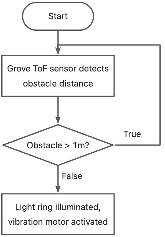
Before officially writing the program, I planned the functions and logic that the software needs to implement and drew the following functional implementation flow chart using Visio:
Because Seeeduino XIAO supports Arduino IDE, I chose to program in the Arduino IDE. Most of the hardware provided by Seed Technology is open source, and they offer excellent documentation support for their products. Thus, during the programming process, I found the corresponding open-source hardware Wiki on the Seeedstudio official website, downloaded the relevant library files (note: library files are a collection of specific functionalities provided by developers that can be used by simply calling them, without having to rewrite the code), and referred to the example routines of the used modules. I completed the program swiftly.
After the program was written and compiled successfully, I connected the Seeeduino XIAO to the computer via a Type-C connection and downloaded the written code to the Seeeduino XIAO through the Arduino IDE. Once the code was successfully uploaded, the prototype was completed.

5. Prototype Testing and Optimization


After completing the prototype, it was time for testing. First, I needed to test whether the prototype implemented the basic functionality, i.e., whether it would sound and light an alarm when a person was detected within a one-meter range. Then, I had to use it in an actual scenario to see if the user experience was good enough. If it could meet the product’s requirements and definition satisfactorily, the product prototype could be deemed successful, and the next step in product development could be initiated. Of course, if issues were found during testing, adjustments and improvements were required, followed by retesting. This process is repeated until the product prototype meets the requirements, and the final scheme is determined.
Finishing the prototype is just the first step in making a successful product. The birth of each product requires a lot of effort, continual trial and error, and adjustment to achieve the best results. The final success of a product, in addition to meeting user needs, also needs to withstand many market tests. This requires students, when beginning to learn to make products, to always maintain the spirit of a craftsman, while also keeping a keen sense for the market, and learning knowledge beyond the product itself. There is a long way to go, and I hope everyone can stick to their original intentions, keep exploring, and ultimately make successful products.
The source code of the program is as follows:
#include <Grove_LED_Bar.h>
#include "Seeed_vl53l0x.h"

const int Buzzer = 8;//Vibration motor connected to D8
Grove_LED_Bar bar(0, 1, 0, LED_CIRCULAR_24);  //Grove-LED ring connected to D0
Seeed_vl53l0x VL53L0X;  //Grove-tof distance sensor connected to IIC (D4/D5)

#if defined(ARDUINO_SAMD_VARIANT_COMPLIANCE) && defined(SerialUSB)
#define SERIAL SerialUSB
#else
#define SERIAL Serial
#endif


void setup() {
    bar.begin();

    pinMode(Buzzer, OUTPUT);
    digitalWrite(Buzzer, LOW);   // turn the Buzzer on (HIGH is the voltage level)
    // Turn off all LEDs
    bar.setBits(0x0);

    VL53L0X_Error Status = VL53L0X_ERROR_NONE;
    SERIAL.begin(115200);
    Status = VL53L0X.VL53L0X_common_init();
    if (VL53L0X_ERROR_NONE != Status) {
        SERIAL.println("Starting VL53L0X measurement failed!");
        VL53L0X.print_pal_error(Status);
        while (1);
    }

    VL53L0X.VL53L0X_long_distance_ranging_init();

    if (VL53L0X_ERROR_NONE != Status) {
        SERIAL.println("Starting VL53L0X measurement failed!");
        VL53L0X.print_pal_error(Status);
        while (1);
    }

}

void loop() {

    VL53L0X_RangingMeasurementData_t RangingMeasurementData;
    VL53L0X_Error Status = VL53L0X_ERROR_NONE;

    memset(&RangingMeasurementData, 0, sizeof(VL53L0X_RangingMeasurementData_t));
    Status = VL53L0X.PerformSingleRangingMeasurement(&RangingMeasurementData);
    if (VL53L0X_ERROR_NONE == Status) {
        if (RangingMeasurementData.RangeMilliMeter >= 2000) {
            SERIAL.println("Out of range!!");
            digitalWrite(Buzzer, LOW);   // turn the Buzzer off (LOW is the voltage level)

            // Turn off all LEDs
            bar.setBits(0x0);

        }
        else if (RangingMeasurementData.RangeMilliMeter <= 1000) {
            digitalWrite(Buzzer, HIGH);   // turn the Buzzer on (HIGH is the voltage level)
            // Turn on all LEDs
            bar.setBits(0b111111111111111111111111);

            SERIAL.print("Distance:");
            SERIAL.print(RangingMeasurementData.RangeMilliMeter);
            SERIAL.println(" mm");
        }
        else {
            digitalWrite(Buzzer, LOW);   // turn the Buzzer off (LOW is the voltage level)

            // Turn off all LEDs
            bar.setBits(0x0);

            SERIAL.print("Distance:");
            SERIAL.print(RangingMeasurementData.RangeMilliMeter);
            SERIAL.println(" mm");
        }

    }
    else {
        SERIAL.print("Measurement failed!! Status code =");
        SERIAL.println(Status);
        digitalWrite(Buzzer, LOW);   // turn the Buzzer off (LOW is the voltage level)

        // Turn off all LEDs
        bar.setBits(0x0);
    }

    delay(250);

}
Get this program from Github
https://github.com/mouseart/XIAO-Mastering-Arduino-and-TinyML/tree/main/code/L7_tof_XIAO_en